2.4.8 Chimney connection/chimney system
EN 303-5 specifies that the entire flue gas system must be designed to prevent,
wherever possible, damage caused by seepage, insufficient feed pressure and
condensation. Please note in this respect that flue gas temperatures lower than 160K
above room temperature can occur in the permitted operating range of the boiler.
The flue gas temperatures (for clean systems) and additional flue gas values can be
found in the table below.
The connection between the boiler and the chimney system should be as short as
possible. The upward angle of the connection should not exceed 30 - 45°. Insulate the
connection. The entire flue gas system - chimney and connection - should be
calculated in accordance with EN 13384-1.
Local regulations and other statutory regulations also apply.
NOTICE! The chimney must be authorised by a smoke trap sweeper or chimney
sweep.
Draught limiter
We generally recommend the installation of a draught limiter. A draught limiter must
be installed if the maximum permissible feed pressure as given in the boiler data for
planning the flue gas system is exceeded.
NOTICE! Install the draught limiter directly under the mouth of the flue line, as the
pressure is constantly low at this point.
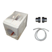
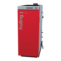
Measuring port
For measuring the emissions of the system, a suitable measuring port must be
installed in the connecting piece between the boiler and chimney system.
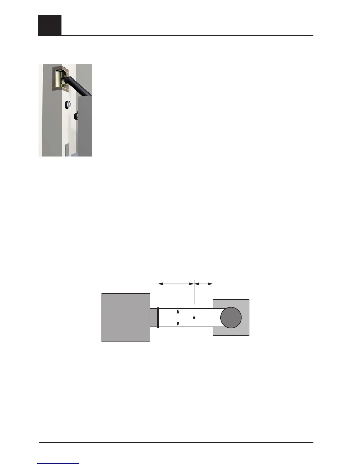
In front of the measuring port (M) a straight inlet section should be located at a
distance corresponding to about twice the diameter (D) of the connecting piece. A
straight outlet section at a distance corresponding to about the single diameter of the
connecting piece should be provided after the measuring port. The measuring port
must remain closed whenever the system is in operation.
Ensure that the outside diameter of the sampling probes in the measuring port can
accommodate up to 13 mm. To avoid the ingress of false air, the diameter of the
measuring port must not exceed 21 mm.
2
Safety
Design Information
14 Froeling GesmbH | A-4710 Grieskirchen, Industriestraße 12 | www.froeling.at
 Loading...