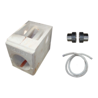
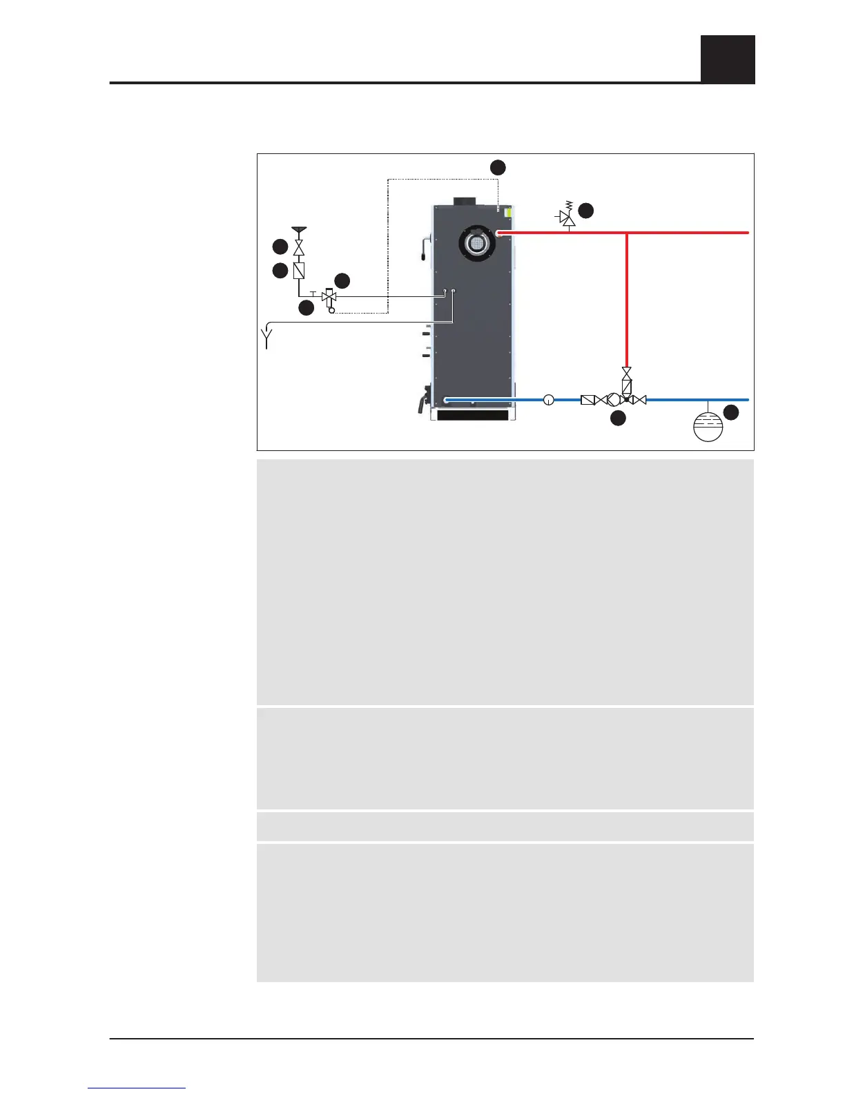
1 Thermal discharge valve
▪
The thermal discharge safety device must be connected in accordance with
ÖNORM/DIN EN 303-5 and as shown in the diagram above
▪ The discharge safety sensor must be connected to a pressurised cold water
mains supply (temperature ≤ 15°C) in such a way that it cannot be shut off
▪ A pressure reducing valve (1.5) is required for a cold water pressure of ≥ 6 bar
Minimum cold water pressure = 2 bar
1.1 Sensor of thermal discharge safety device
1.2 Thermal discharge valve (opens at approx. 95°C)
1.3 Cleaning valve (T-piece)
1.4 Dirt trap
1.5 Pressure reducing valve
1.6 Free outlet without counter pressure
2 Safety valve
▪ Safety valve as per ÖNORM EN ISO 4126-1, diameter as per EN 12828 or
national regulations
▪ The safety valve must be installed in an accessible place on the heat generator or
in direct proximity in the flow pipe in such a way that it cannot be shut off
3 Return temperature control
4 Diaphragm expansion tank
▪
The diaphragm pressurised expansion tank must conform to EN 13831 and hold
at least the maximum expansion volume of the system’s heated water including a
water seal
▪ Its size must comply with the design information in EN 12828 - Appendix D
▪ Ideally it should be installed in the return line. Follow the manufacturer’s
installation instructions
Assembly
4
Connecting the hydraulic safety devices
Installation Instructions S3 Turbo | M1081217_en 57
 Loading...