1.3.9 Requirements for the chimney connection
The chimney connection must be big enough to channel flue gases from the building.
The whole flue gas system must be designed to prevent possible seepage, insufficient
feed pressure and condensation.
The manufacturer recommends fitting a draft regulator to limit the pressure to 0.12
inch WC (30 Pa). The draft regulator should be fitted directly on the chimney
connection where the pressure is very low.
The boiler must be connected to a brick chimney or a shop-made chimney in
accordance with UL 103 HT (ULC S629 in Canada). The chimney must be clean and
in good condition at the time of installation.
The pipe unions within the chimney must be made of stainless special steel (with 304,
316 or 321 alloys). The flue gas connection pipe must be made of untreated steel or
stainless steel with a thickness of 24 Gauge. The minimum rise of the pipe must be ¼"
per foot for the progression towards the chimney. The chimney and the flue gas
connection pipe must have a diameter of at least 6" (150 mm). The individual pipe
sections must be joined together with at least three self-tapping screws and the joins
sealed using high-temperature silicone. The flue gas pipe must not contain more than
two 90° bends.
All connections must conform to NFPA 211. Consult your local chimney sweep for the
installation and install the boiler in accordance with the applicable local regulations.
The chimney connection, ventilation ducts and fresh air openings must not be closed
over or blocked.
The flue gas pipe must not be displaced by an attic, loft, fuel store or similar areas.
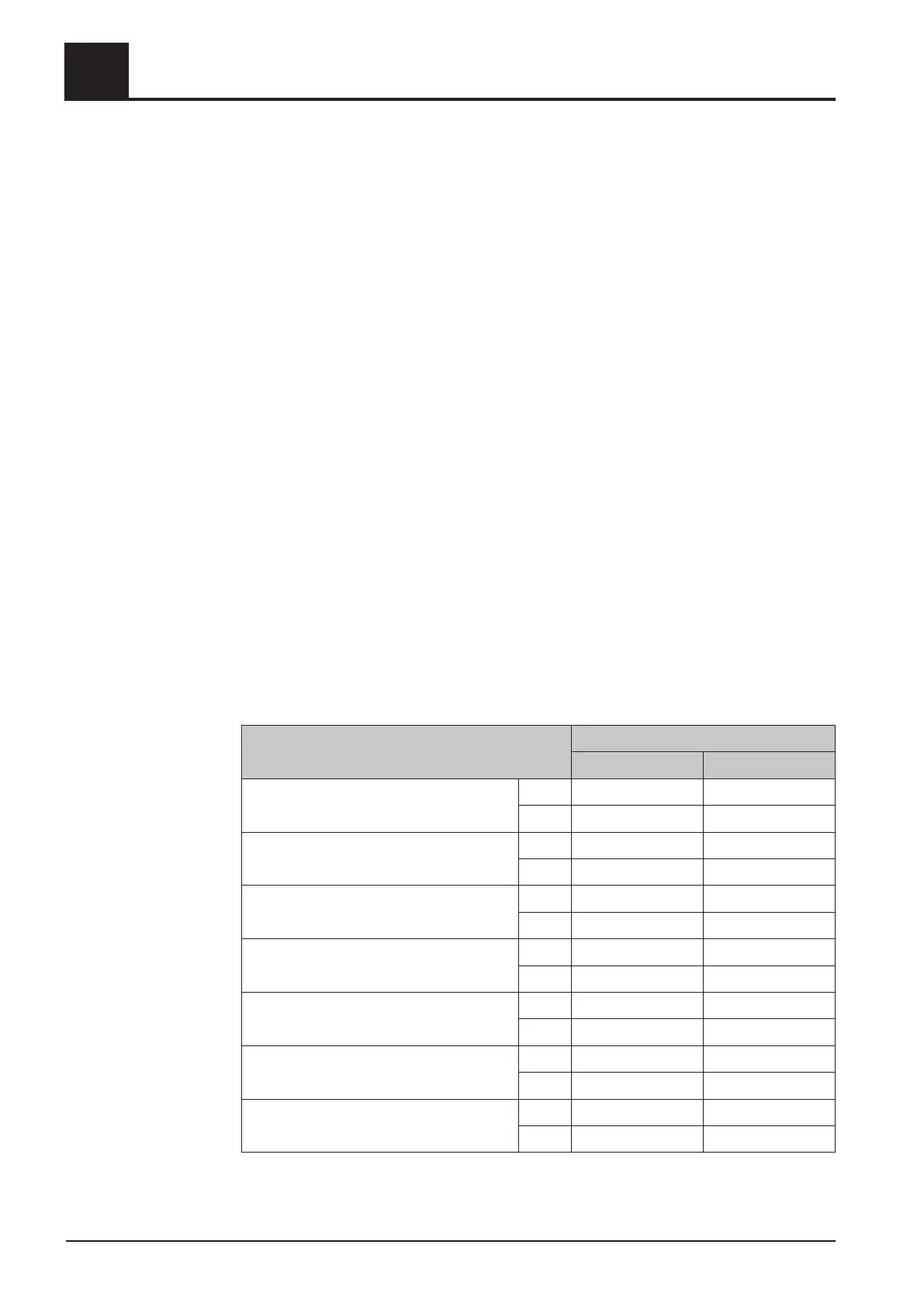
Basic data for designing the chimney connection
Description S3 Turbo
30 50
Flue gas temperature at nominal load °C 220 220
°F 430 430
Flue gas temperature at partial load °C 150 150
°F 300 300
Flue gas mass flow at nominal load kg/h 76 122
lb/h 167 270
Flue gas mass flow at partial load kg/h 43 65
lb/h 95 143
Required feed pressure at nominal load Pa 8 8
in WC 0.03 0.03
Maximum permissible feed pressure Pa 30 30
in WC 0.12 0.12
Flue pipe diameter mm 150 150
inches 6 6
1
Safety
Requirements at the place of installation
12 Froling GesmbH | A-4710 Grieskirchen | www.froeling.com
 Loading...