3.6.1 Wiring the ID fan
❒ Secure the cable leadthrough with a nut in one of the free cut-outs on the terminal
block
❒ Remove lugs on the cover on the occupied positions with a suitable tool
❒ Secure cover to the terminal block
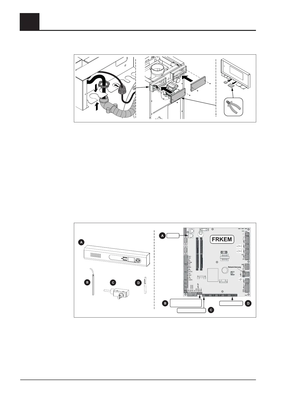
3.6.2 Wiring
❒ Run the cable of the flue gas temperature sensor, boiler sensor, induced draught,
STL, display and door switch to the controller
➥ Tuck any extra cable into the cable duct
❒
Connect the components according to the power connection diagram
➥ The flexible sheathed cable must be used for the wiring; this must be of the
correct size to comply with applicable regional standards and regulations!
BUS (3)
Flue gas
temperature sensor (15)
Door switch DCS (16)
Boiler sensor (25)
Connect the following components on core module:
❒
A: Display (3)
❒ B: Flue gas temperature sensor (15)
❒ C: Door switch DCS (16)
❒ D: Boiler sensor (25)
3
Assembly
Power connection and wiring
64 Froling GesmbH | A-4710 Grieskirchen | www.froeling.com
 Loading...