PC board
No. Push-pull unit SR41 SR43
1)
No calibration under load (St2) is required
3)
Software enabling required
4
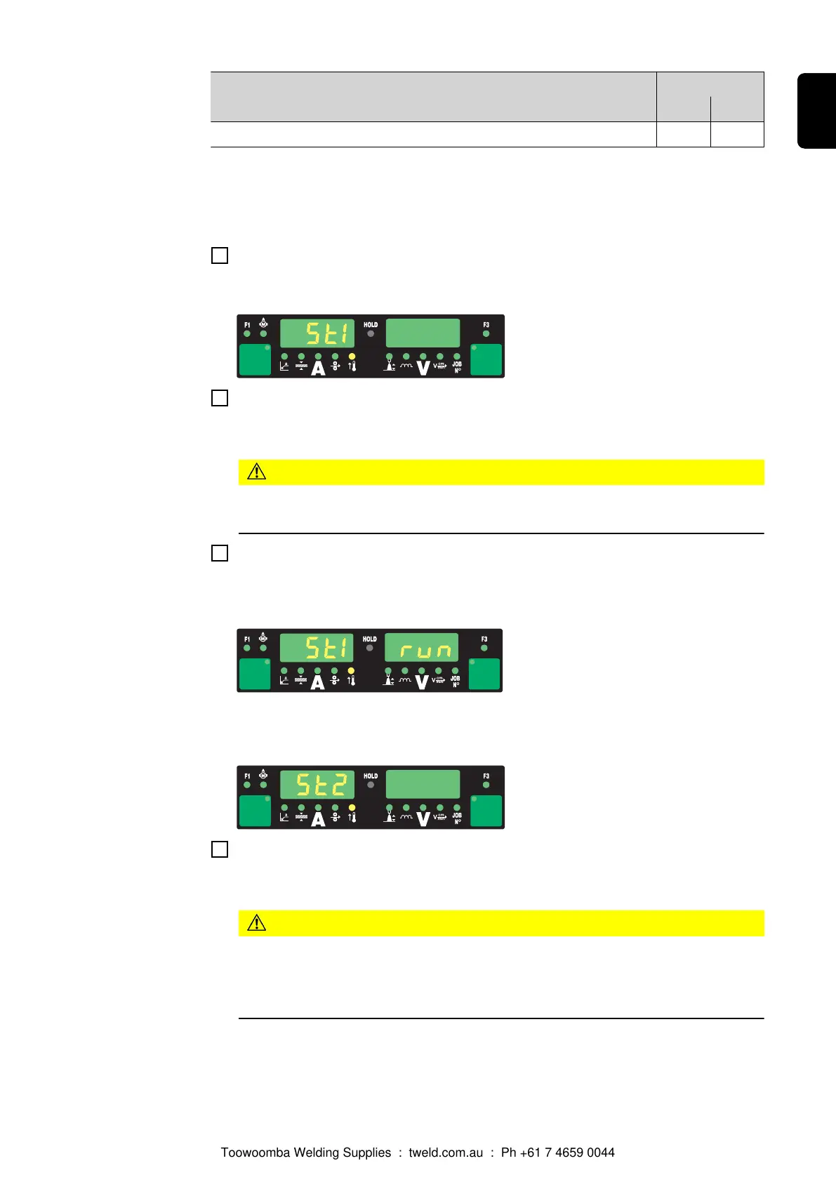
Press the “Feeder inching” button or the torch trigger
"St1" is displayed on the left-hand digital display
5
Disengage the drive units of both wire-feed unit motors (e.g. welding torch and wire-
feed unit) - the wire-feed unit motors must not be under load (push-pull calibration -
open circuit)
CAUTION!
Risk of injury from rotating cogs and drive parts.
Keep hands away from rotating cogs and the wire drive.
6
Press the “Feeder inching” button or the torch trigger
The wire-feed unit motors are calibrated while not under load. During the calibration
process "run" is displayed on the right-hand digital display
Once the calibration - in the unloaded state - has been completed, the digital display
will read "St2".
7
Engage the drive units of both wire-feed unit motors (e.g. welding torch and wire-
feed unit) once again - the wire-feed unit motors must be under load (push-pull calib-
ration - engaged)
CAUTION!
Risk of injury from wire electrode emerging at speed and from rotating cogs
and drive parts.
Hold the welding torch so that it points away from your face and body. Keep hands
away from rotating cogs and the wire drive.
165
EN
Toowoomba Welding Supplies : tweld.com.au : Ph +61 7 4659 0044
 Loading...