24
Replacing the secondary diode
Replacing the
secondary diode
Open housing as described in chapter
"Opening the housing".
Remove the BPS 170 / 190 PC board
in accordance with the chapter "Remo-
ving the BPS 170 / 190 PC board".
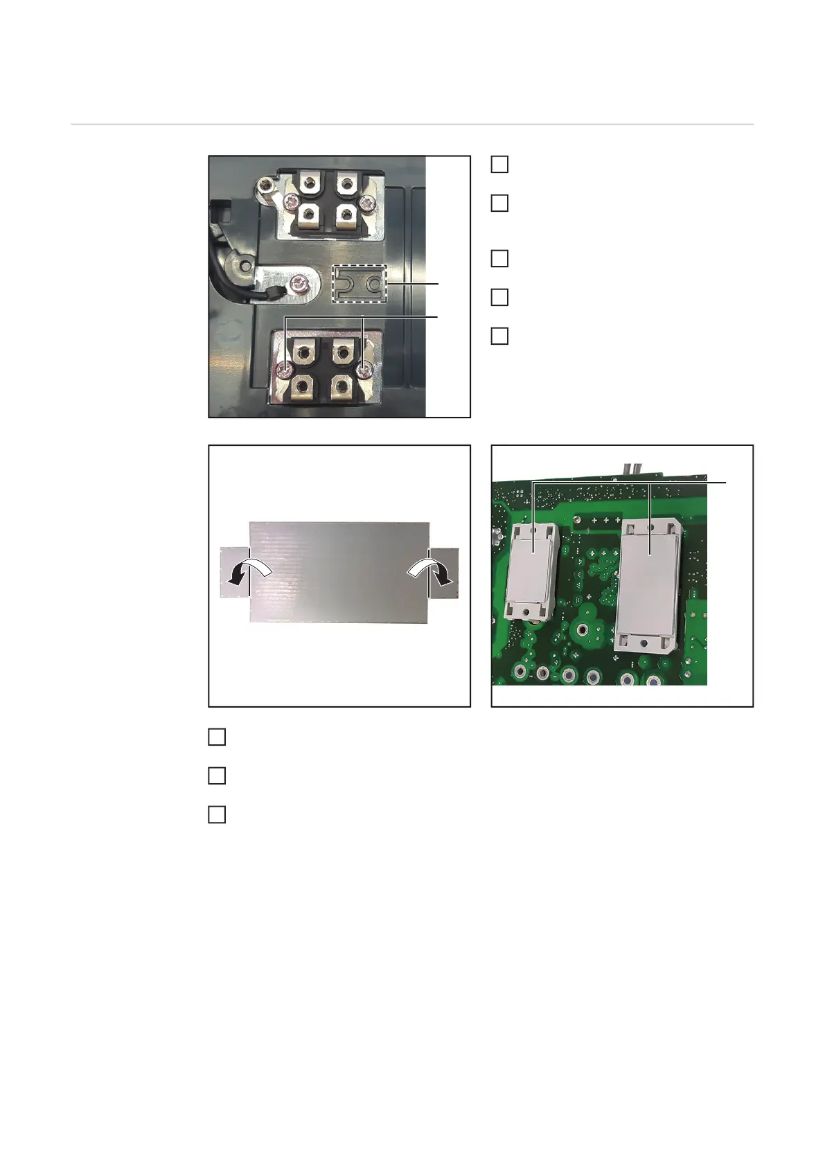
Loosen the 2 M4x13 TX20 screws (1)
of the defective diode.
Clean the heat sink and modules on
the BPS PC board.
Place the new diode on the heat sink
as per stamping (2) and secure with 2
M4x13 TX20 screws (1):
Pretighten to 0.9 Nm.
Final tightening torque = 1.3 Nm.
Bend the tab (3) and install the thermal conducting foils (4) on the modules of the BPS
170 / 190 PC board as shown.
Install the BPS 170 / 190 PC board according to the chapter "Installing the BPS 170 /
190 PC board".
Close housing as described in chapter "Closing the housing".
7
8

 Loading...


