20
Replacing the BPS 170 / 190 PC Board
Removing the
BPS 170 / 190 PC
Board
Open housing as described in chapter
"Opening the housing".
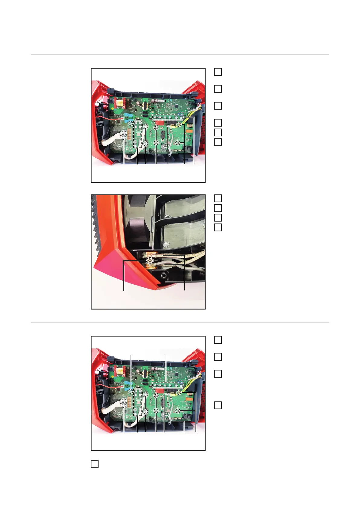
Disconnect all plugs and cables on the
BPS 170 / 190 PC board.
Loosen 4 M5x12 TX25 screws (1) of
the secondary transformer lines.
Loosen 16 M4x8 mm TX20 screws (2).
Loosen 4 M4x13 mm TX20 screws (3).
Loosen the M4x12 TX20 spacer (4).
Loosen the 4x20 mm TX20 screw (5).
Remove the lines (6) from the terminal.
Remove the BPS 170 / 190 PC board.
Clean the heat sink.
Installing the BPS
170 / 190 PC
Board
Remove the blister cover from the mo-
dules.
Place the new BPS 170 / 190 PC board
on the cleaned heat sink and align it.
Install the modules with 4 M4x13 TX20
screws (3):
tighten to 0.5 Nm.
Final tightening torque = 1.9 Nm.
Install 2 M4x12 spacers(4).
Tightening torque = 2.1 Nm.
Install 8 M4x8 M4x12 screws (2).
Tightening torque = 1.5 Nm.
(1)
(1)
(2)
(3)
(4,5)
(3)
(7)
(6)
(4)

 Loading...


