38
Electrical Tests
Ground conduc-
tor resistance
- The ground conductor resistance must
not exceed 0.3 (with a mains cable
length of up to 5 m plus 0.1 for each
additional 7.5 m max. 1 each
- All housing components must be in-
stalled
- The measurement current must be at
least 200 mA - 10 A recommended
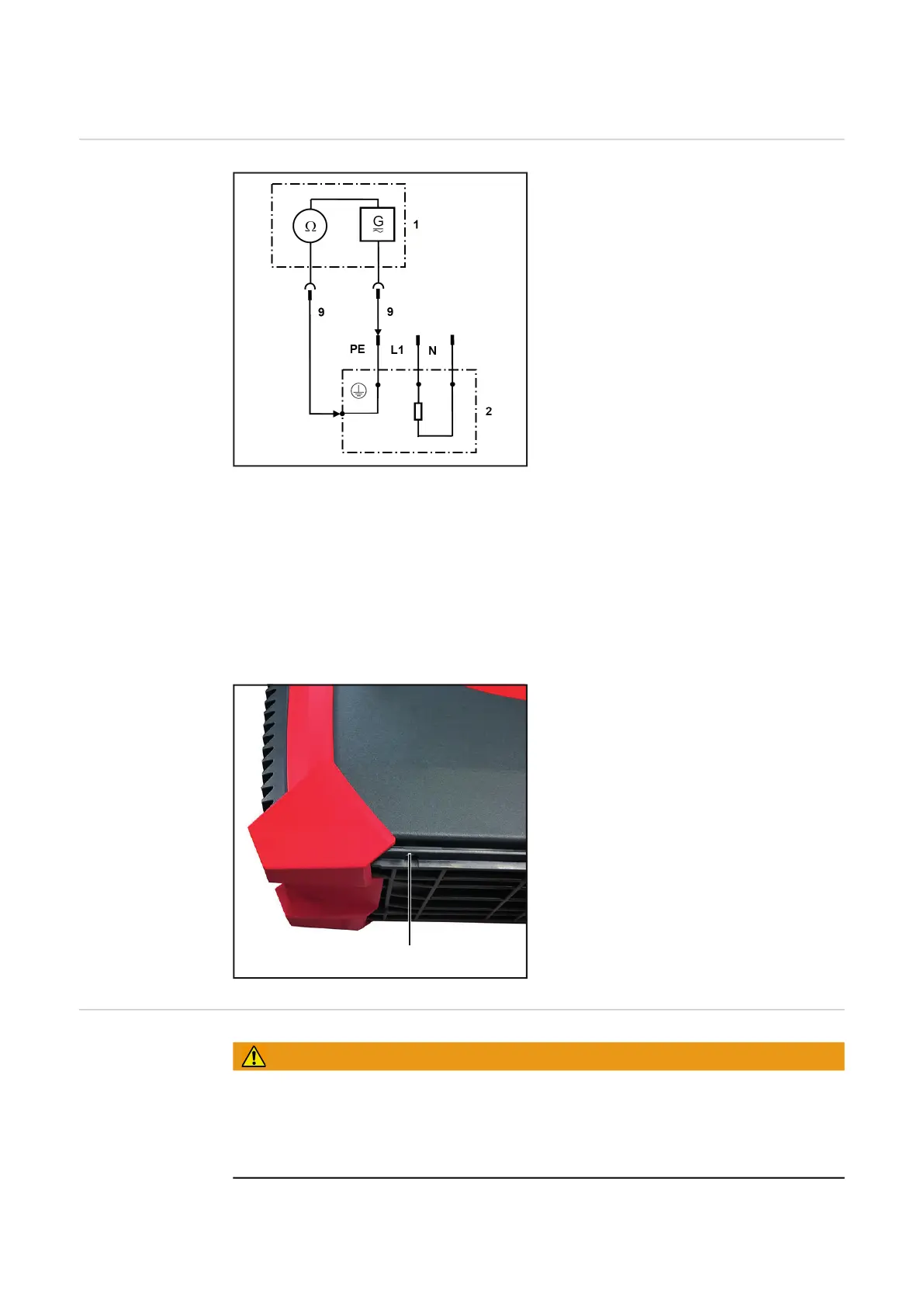
Key:
1 Measuring instrument
2 Test object
9 Measuring line
- Mains cable:
Measured from the ground conductor contact of the mains plug to a reliable grounding
point of the device (e.g. bare point on the casing under the rear of the housing)
- During this measurement, bend, flex, and twist the mains line to detect any inter-
ruptions in the ground conductor.
- Particular attention should be paid to the cable entries in the housing
- Device:
Measured from the ground conductor contact of the mains cable or from a reliable
ground point to the gas solenoid valve.
- The highest measured value must be entered in the log
- Remove the paint from the casing as
shown at the defined point (1) to carry
out the ground conductor measure-
ment.
Insulation resis-
tance
WARNING!
The test voltage is 500 V DC.
Do not touch the test object during the test!
Make sure that the capacitors between the primary and the ground are no longer charged
after the test. If necessary, discharge the capacitors with a suitable resistor, e.g. 10 k / 5
W

 Loading...


