26
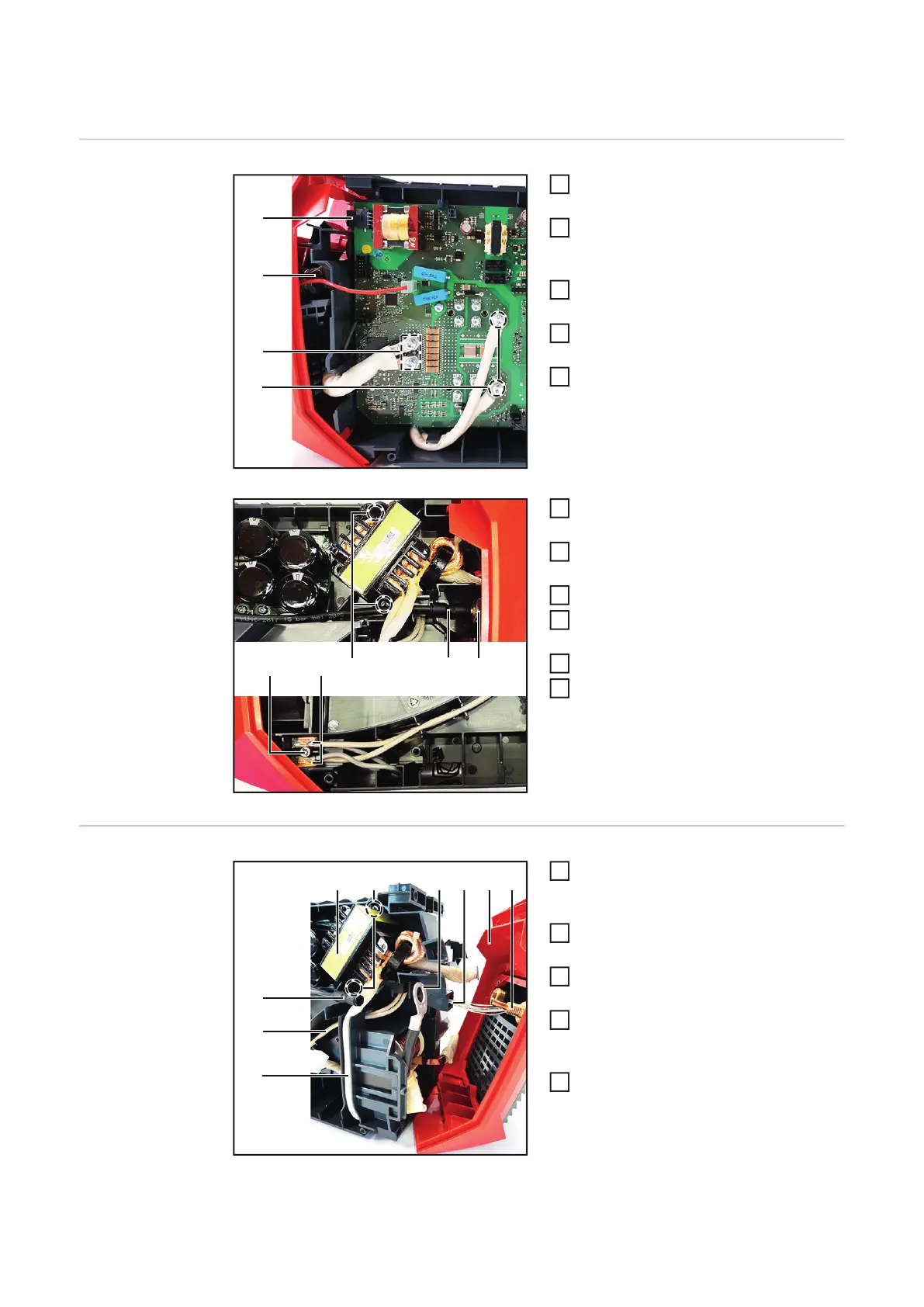
Replacing the Transformer
Removing the
transformer
Open housing as described in chapter
"Opening the housing"
Remove the HF 190 PC board accor-
ding to the chapter "Replacing the HF
190 PC board".
Disconnect the remote control cable
(1).
Loosen 4 M5x12 TX25 screws (2) for
the transformer cables.
Loosen hexagonal bolt SW 19 mm (3).
Disconnect push-in connection (4)
from the power connector.
Loosen nut (5) size 19 mm and remove
front panel.
Loosen 4x20 mm TX20 screw (6).
Disconnect the transformer cables (7)
from the terminals.
Loosen 2 4x20 TX20 screws (8)
Remove the transformer.
Installing the
transformer
Insert the transformer (4) and secure it
with 2 4x20 TX20 screws (5).
Tightening torque = 2.1 Nm.
Route secondary (1) and primary (2)
transformer cables as shown.
Position the front panel (8) and insert
the remote line (7) as shown.
Install the cable lug (6) with nut size 19
mm and washer on the power connec-
tion (9).
Connect push-in connection (3) to the
power connection (9).
(8)
(2)
(1)
(4)
(3)
(5) (6) (7) (9)

 Loading...


