10
BACKGROUND CURRENT DIAL I
2
l The setting for the background current is made as a percen-
tage of the value set for the pulsing current I
1
DUTY CYCLE DIAL %
l Setting dial for pulse / interval relationship = this dial is for
setting the relationship, in percentage terms, between the
pulsing current phase and the background current phase.
Setting-examples
Duty cycle dial
is in scale position 10,
l Short pulsing current phase of 10 %
l Long background current phase of 90 %
l Low degree of heat impact.
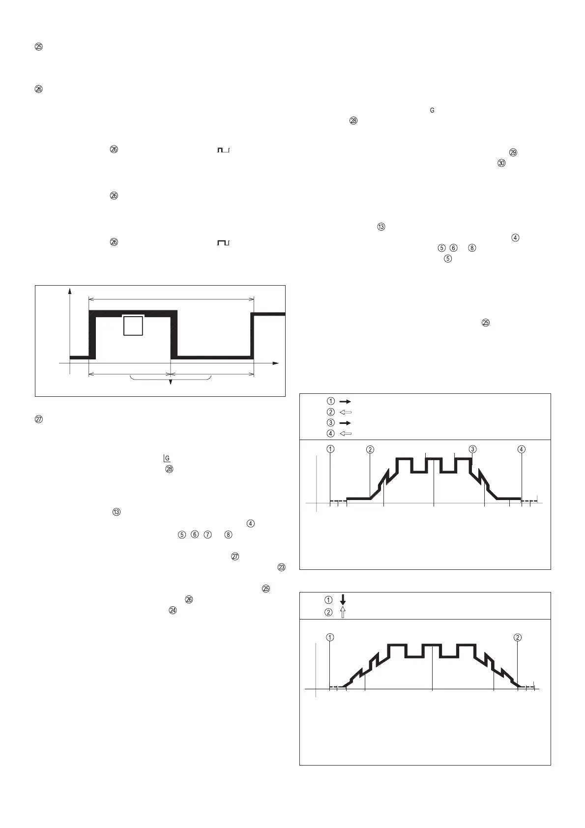
Duty cycle dial is in scale position 50, (see Fig.11)
l Pulsing current phase and background current phase are
equally long (each 50 %)
l Means medium degree of heat impact.
Duty cycle dial
is in scale position 90,
l Long pulsing current phase of 90 %
l Short background current phase of 10 %
l High degree of heat impact.
FREQUENCY RANGE SWITCH
OPERATING MODE: Regulation of pulse current I
1
using a
remote control
l Link the connecting socket on the power source and the
remote-control unit socket
electrically with the remote
control cable.
l Plug in the plug-in connections the right way round, and
screw the coupling ring on as far as possible.
l LED indicator blinks up on the power source
l Set desired operating mode with function button
l The appropriate LED-indicator , , or lights up
l Pre-select the frequency range (0.2 - 2Hz, 2 - 20Hz, 20 -
200Hz, 200 - 2000Hz) with the range switch
.
l The pulsing current I
1
is set continuously with setting dial
l The setting for the background current I
2
is made as a
percentage of the pulsing current I
1
, with setting dial
l To select the duty cycle use dial
l Set the pulse frequency dial to the desired value.
l Mean welding-current amperage is indicated on display A
l The downslope parameter is set directly on the power
source.
In the 4-step operating mode, the pulse phase begins as soon
as the operator releases the torch trigger in the up-slope. As
can be seen in Fig. 12, pulsing also takes place in the down-
slope.
Important! If you wish to be able to switch from main current to
crater-fill current while in pulsed-arc mode (without interrupting
welding), use:
l 4-step mode and a FRONIUS TIG torch with double control-
switch function, or:
l special 4-step mode and a non-Fronius TIG torch
Please see chapter "Description of controls" for more details of the
4-step and special 4-step operating modes.
Fig. 11 Setting-example Duty-Cycle in scale position "50"
Gas pre-flow time
OPERATING MODE: Regulation of pulse current I
1
using
TR 52mc remote-control pedal unit
It is particularly advantageous with manual TIG welding in
cases where it is necessary to alter the welding pulse current
during the welding operation. (Where the welder is dealing with
materials of different strengths, for example).
l Link the connecting socket on the power source and the
socket
on the remote-control pulsing unit electrically with
the remote control cable.
l A remote control cable of the same type may be used for
linking the remote-control pulsing unit (socket ) electri-
cally to the remote control pedal unit (socket ).
l Plug in the plug-in connections the right way round, and
screw the coupling ring on as far as possible.
l When the TR 52mc remote-control pedal unit is connected,
the machine automatically switches over to 2-step operati-
on.
l LED indicator blinks up on the power source
l Set desired operating mode with function button
l The appropriate LED indicator , or lights up -operating
mode electrode (LED indicator ) is possible
l The mean welding-current amperage is indicated on display
A. - No "Hold" function
l To initiate the ignition process, gently step on the pedal.
l The level of the start arc current, the pulse current I
1
and the
final crater current can also be controlled from the pedal.
l The base current I
2
that is set using the dial on the TR 50mc
is a constant percentage of the value of the pulse current I
1
.
l When the welder takes his foot right off the pedal, the welding
current is switched off, thus interrupting the welding opera-
tion.
l Gas post-flow time elapses.
Pedal pressed down = welding "ON"
Foot off the pedal = welding "OFF"
I
1
I
2
t
I
Fig. 13 Functional sequence in pulsed-arc operation, in conjunction with the
TR 52mc remote-control pedal unit (2-step)
Fig. 12 Functional sequence in pulsed-arc welding operation using TR 50mc (4-step)
Release the torch trigger
Pull back and hold down the trigger once again
Release the torch trigger
Pull back torch trigger and hold down
I
1
I
2
f (Hz)
I
S
I
E
I
t
Start of cycle
Arc ignition
with start arc I
S
Pulsing current-rise
via up-slope
Pulsed-arc
welding operation
I
1
, I
2
/ f / Duty-Cycle
End of welding
Crater-fill current I
E
Gas post-flow time
Current-drop
(with pulse) via
down-slope
Gas pre-flow time
Start of cycle
Pulsing current-rise,
can be regulated
by pedal
Pulsing current-rise,
can be regulated
by pedal
End of welding
Gas post-flow time
Pulsing current-drop,
can be regulated
by pedal
Pulsed-arc
welding operation I
1
, I
2
O
O
I
2
I
1
Duty-Cycle
0
I
t
T= 1/f
(Hz)
50% 50%
 Loading...


