11
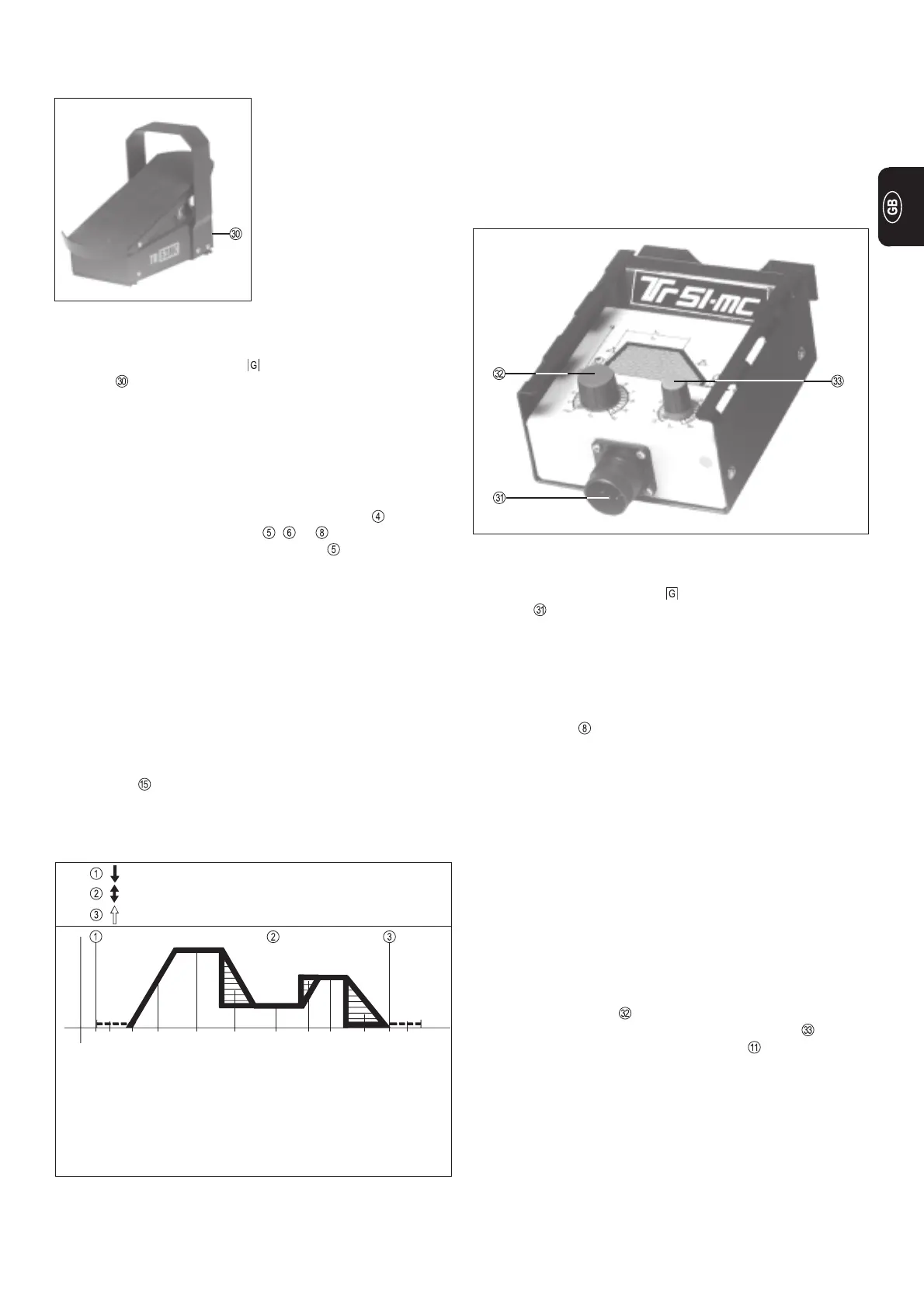
Fig. 16 TR 51mc remote control spot-welding unit
Connecting the remote control unit:
l Link the connecting socket on the power source and the
socket on the remote-control unit electrically with the remote
control cable.
l Plug in the plug-in connections the right way round, and screw
the coupling ring on as far as possible.
Functional description:
l The machine automatically switches over to 2-step operation
l LED indicator lights up
l The current drop time is set directly on the power source
l A special - insulated - spot-welding nozzle is used, which is
mounted on the cone.
l Depending on the size of spot-weld required, mount the tungs-
ten electrode approx. 2 - 3 mm back from the edge of the nozzle
l Set spot-welding current and time on the remote-control unit.
l Place the torch on the workpiece and gently press down onto
the base material
l To carry out the spot-weld actuate the torch trigger.
(Make sure there is no air-gap!)
The automatic spot-welding sequence is as follows:
l Pull back and release the torch trigger.
l Gas pre-flow time elapses.
l Arc ignites with start-arc current.
l Current rises via the set up-slope to the spot-welding current
value set on the dial .
l The spot-welding time (0,1 - 8 secs.) set on the dial elapses.
l The current drops via the down-slope (dial ) to the final crater
current.
l The gas post-flow time elapses.
Important! In the event of any trouble, the welder can manually
interrupt the automatic spot-welding sequence by pulling back and
releasing the trigger again!
TR 51MC REMOTE CONTROL SPOT-
WELDING UNIT
Standard welding of thin sheet metal constructions in such a way
that they do not rust is often not possible due to severe warping of
the material. This is where spot welding comes into its own.
Similarly, problem welds, such as joins which are only accessible
from a single side, can easily be dealt with using the TIG spot-
welding process.
TR 52MC REMOTE CONTROL PEDAL UNIT
Connecting the remote control unit:
l Link the connecting socket on the power source and the
socket on the remote-control unit electrically with the remote
control cable.
l Plug in the plug-in connections the right way round, and screw
the coupling ring on as far as possible.
Functional description:
l When the TR 52mc remote-control pedal unit is connected, the
machine automatically switches over to 2-step operation.
l Set desired operating mode with function button
l The appropriate LED indicator , or lights up -
operating mode electrode (LED indicator ) is possible
l The mean welding-current amperage is indicated on display A.
- No "Hold" function
l Gas pre-flow time and gas post-flow time are set directly at the
power source.
l To initiate the ignition process, gently step on the pedal.
l The level of the start arc current, the main current I
H
and the final
crater current can also be controlled from the pedal.
l When the welder takes his foot right off the pedal, the welding
current is switched off, thus interrupting the welding operation.
Gas post-flow time elapses.
Limitation of main current
If the maximum welding current value is set internally on the main
current I
H
dial then the remote control pedal may be depressed
to its full extent without the main welding current exceeding the pre-
set value. This has the advantage that the selected current range
is covered by one complete depression of the foot pedal.
Due to the fact that workpie-
ces are often awkwardly
shaped, it is often necessary
to alter the amperage in the
course of the welding operati-
on. (e.g. repairing the edges of
tools, improvements to cutting
dies).
The TR52mc pedal remote-
control unit is designrd to be
used for jobs such as these.
Pedal pressed down ð welding "ON"
Current is regulated by pedal
Foot off the pedal ð welding "OFF"
I
O
I
H
I
H
t
Fig. 15 Functional sequence with the TR 52mc remote control pedal unit (2-step)
Gas pre-flow time
Arc is ignited with
minimum current
End of welding
Gas post-flow time
Start of cycle
Current-rise
can be regulated by pedal
Max. welding current,
limited by main-current dial
(internally)
Current-drop,
can be regulated by pedal
Reduced welding current
Current-rise,
regulated by pedal
Desired welding current
Current-drop,
regulated by pedal
Fig. 14 TR 52mc remote control pedal unit.
 Loading...


