7
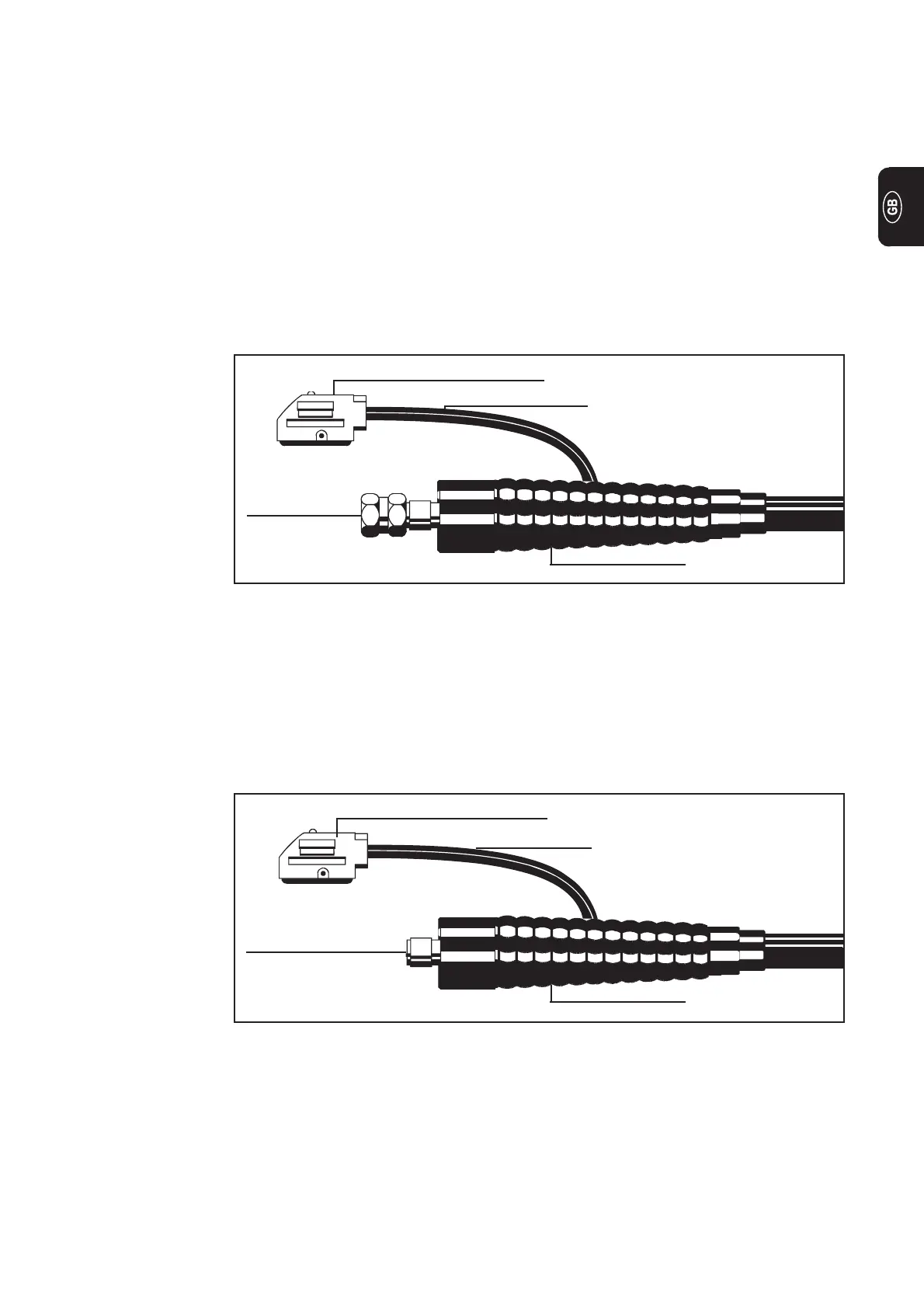
Gas and current
connection
Control plug
Control lead
Fig. 6 Design with central burner connection GWZ: Torch connection gas-cooled
Hose sleeve
- Insert welding torch bayonet connection in the central connection on the equipment
side of the welding torch [A] and lock in place by turning to the right
- Insert control plug in the socket [D] and lock in place
Important! Please see your torch’s instruction manual for technical details on the torch
and for information on torch assembly, care and maintenance.
Assembling a gas-cooled TIG torch
Design with
central burner
connection GWZ
- Pull back the rubber sleeve from the rear of the torch
- Screw the hexagon nut (width across = 21) of the gas+current connection onto the
torch connector point on the machine [A]
and tighten firmly
- Push the rubber sleeve back over the hexagon nut
- Plug the control plug into socket [C] and latch it
Important! Please see your torch’s instruction manual for technical details on the torch
and for information on torch assembly, care and maintenance.
Design with
Fronius central
welding torch
connection F
Fig. 7 Design with Fronius central welding torch connection F: Torch connection gas-cooled
Gas and current
connection
Control plug
Control lead
Hose sleeve
 Loading...


