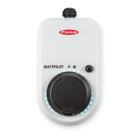
Controls and indicators
Product over-
view
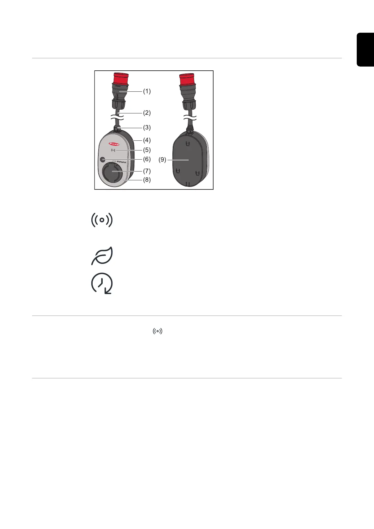
(1) CEE plug
(2) Connection cable
(3) Strain-relief device
(4) Housing
(5) Card reader
(6) Pushbutton
(7) Type 2 junction box
(8) LED ring
(9) Rating plate
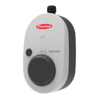
Symbols on front of the device:
Kartenleser
The symbol shows the location of the card reader installed in the device
where ID chips can be authenticated or taught-in or the Wattpilot can
be reset using the reset card.
Eco Mode
This symbol indicates operation in Eco Mode; the first LED lights up
white.
Next Trip Mode
This symbol indicates operation in Betrieb im Next Trip Mode; the
second LED lights up white.
Card reader
Behind the symbol is the card reader for reading ID chips and the reset card.
The card reader uses RFID (radio-frequency identification). RFID is the transmit-
ter‑receiver technology for automatic and contactless identification with radio
waves.
Pushbutton
functions
By pressing the pushbutton, the level of charging current can be adjusted or the
operating mode can be changed.
Press for under 0.5 s
Briefly pressing the pushbutton changes the operating mode. The charging
modes are
-
Standard mode
-
Eco Mode
-
Next Trip Mode
The selected charging mode (see Different charging modes on page 26) is indic-
ated by the LED status indicator (see LED status indicator on page 17); in
standard mode, no operating mode LEDs light up.
15
EN
 Loading...