Physical interface Two M6 C-C 5/8 in.
ISO metric screw threads, coarse pitch
ISO 261 and ISO 965. Hole diameter 1/4.
Note: e bolt aachment torque must be tightened to at least 5.6 Nm.
Table 15
Power Cable Pinout
Pin Output Type Description
Pin A –48 V DC Red Wire
Pin B Return Black Wire
2.7.4
RET Port
is RU has one communication interface between antenna line devices. e four RU antenna ports connect to
the antenna with 4.3-10 RF connectors. e RU RET port supports antenna beam adjustment using two
combined RS-485 connectors and DC power circuits (required by 3GPP Technical Specication (TS) 25.461, Layer
1) and AISG 3.0.
Physical interface
■ IEC 60130-9 Ed. 3.0 with screw-ring locking 8 pins, female
■ 5 A on any pin
Electrical interface
■ R
S-485
Based on 3GPP TS 25.461/AISG 3.0
Bit rates: 9.6/38.4/115.2 (kb/s)
■ DC Voltage supply
DC Voltage 28.5 V (Accuracy ±1.5 V on RU connector) is supplied from pin number 6.
Current capability 0…1.0 A (normal range)
Other
■ Lightning protection circuit on RU (refer to
Resistability of Lightning)
IP65 is supported for the function of waterproong with ed cap or connected cable.
No guarantee for waterproof when cap or cable is loose contact or not connected.
Table 16
RET Interface Connector Pin Assignment
Pin Description
1 Not connected
2 Not connected
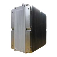
RU Hardware Feature
External Interface
57
Release 1.0 · Issue 1.1, May 2021
Fujitsu and Fujitsu Customer Use Only