In order to reduce power consumption, the RU controls the drain voltage of the power amp in accordance with
the transmission mode. e drain voltage is switched according to the transmission output power of each band.
e transmission output power of each band is checked by the DL Gain value in the M-plane "TX-Array-Carrier"
message.
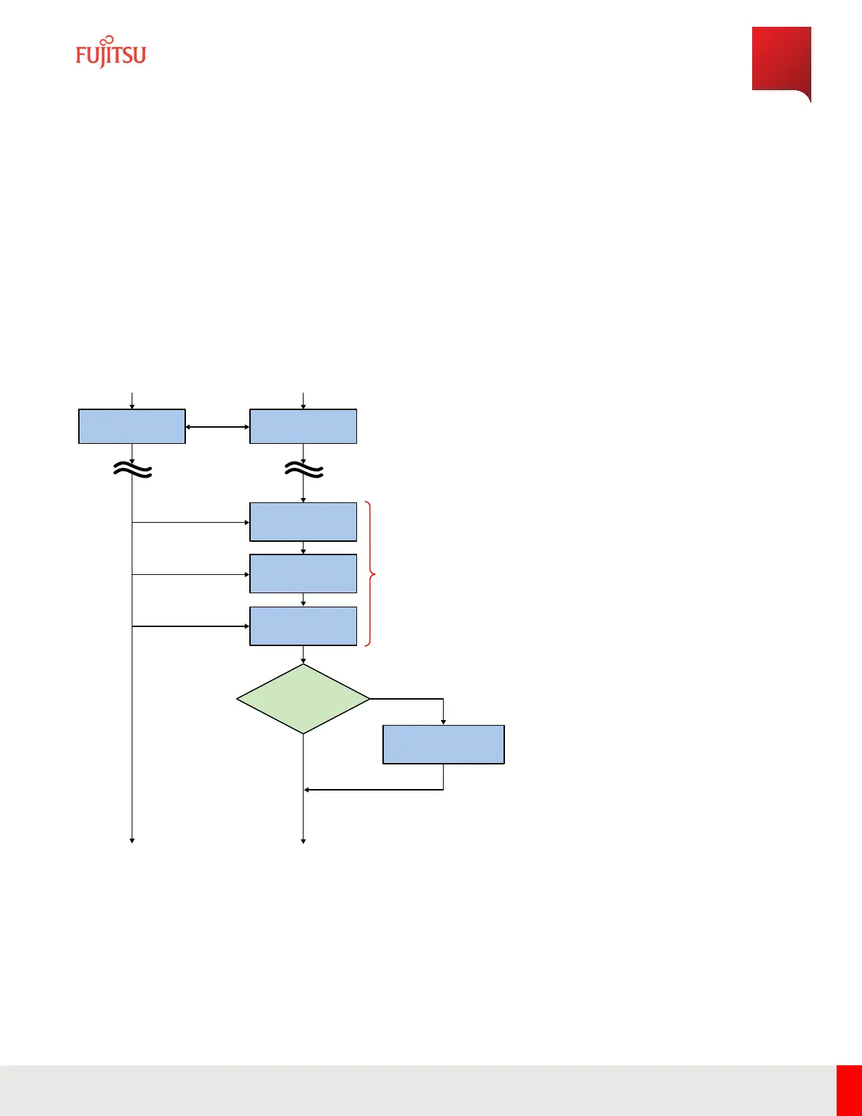
When transmission carrier seing is added or changed during operation and switching of transmission mode
occurs, transmission is turned o to change drain voltage, and transmission control is performed again aer
switching drain voltage.
e following ow image is sample for 3 carriers, maximum 60 W at n66.
Host System
M-Plane
Established
M-Plane
Established
Port #A n66
DL Gain: Maximum
Output Power -3db
Tx-Array-Carrier-01
Message
Tx-Array-Carrier-02
Message
Tx-Array-Carrier-03
Message
Port #A n66
DL
Gain: Maximum
Output Power -6db
Total 3 Carriers
P
ort #A
Maximum Output Power =
47.8dBm (60W)
n66 at Port #A is 60W,
so Port #A Transmit Mode is
(ii)n70 + n66: 20W + 60W
Port #A n66
DL Gain: Maximum
Output Power -6db
M66 Maximum
Outp
ut Power
< 40W?
Switch Power Mode
i) -> (ii)
n70 + n66: 20W + 60W
Dual-Band RU
No
Yes
FNC001700_Rev_01
RU Hardware Feature
TX Control Function
62
Release 1.0 · Issue 1.1, May 2021
Fujitsu and Fujitsu Customer Use Only