Component Names and LED Names
This section describes the operation panel, the drives, the controllers, the power supply units, the host
interfaces, the batteries, and the BUDs of the controller enclosure.
■
Operation Panel
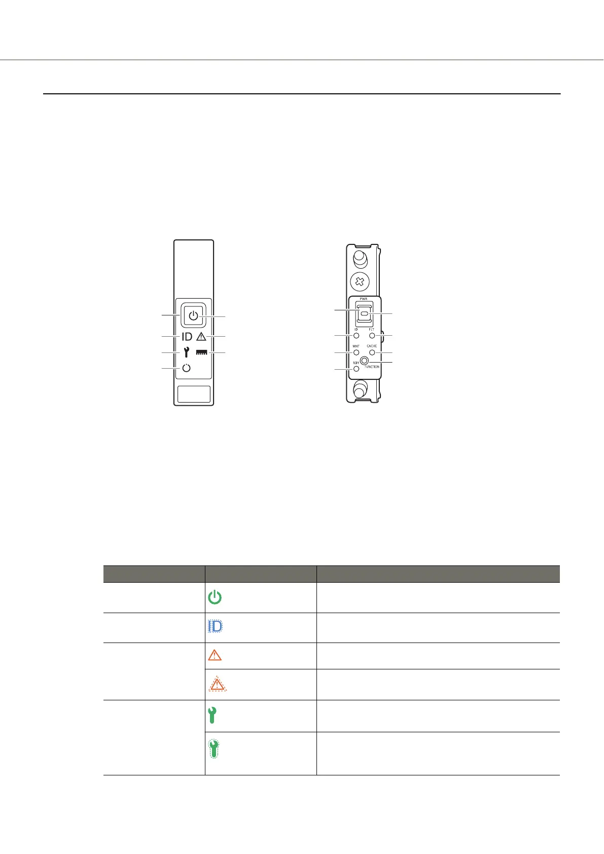
● ETERNUS AF150 S3/AF250 S3
An operation panel has LEDs, a Power switch, and a FUNCTION button.
Figure 13 Operation Panel (ETERNUS AF150 S3/AF250 S3)
1
1
2
With a f
lange cover Without a flange cover
POWER LED
IDENTIFY LED
FAULT LED
MAINTENANCE LED CACHE LED
READY LED
POWER LED
IDENTIFY LED FAULT LED
MAINTENANCE LED CACHE LED
READY LED
1 Power switch
This switch is used to turn on or off the ETERNUS AF
.
2 FUNCTION button
This button is used to switch the maintenance status on or off, to switch the master CM, to initialize
the LAN ports, or to initialize the user settings.
The LEDs turn on or blink to indicate the statuses that are listed below.
Table 9 Status and Meaning of Each LED (Operation Panel [Controller Enclosure for the ETERNUS AF150
S3/AF250 S3
])
LED name LED status Meaning
POWER
(green)
DC power is supplied to the ETERNUS AF.
IDENTIFY
(blinks blue)
The installation location of the ETERNUS AF is identified according to
the instruction that is issued from ETERNUS Web GUI or ETERNUS CLI.
FAULT
(amber)
The ETERNUS AF is in error status.
(blinks amber)
A part of the ETERNUS AF requires preventive maintenance.
MAINTENANCE
(green)
Maintenance for the ETERNUS AF is in progress.
(blinks green)
Maintenance (from ETERNUS Web GUI or ETERNUS CLI) for the
ETERNUS AF is in progress or a status check of the ETERNUS AF
is
necessary.
A. Component Names
Controller Enclosure
71 Operation Guide (Basic)
 Loading...