List of Figures
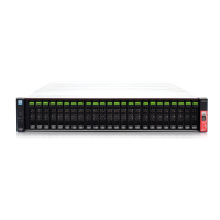
Figure 1 Front View of a Controller Enclosure...........................................................................................................9
Figure 2
Rear View of a Controller Enclosure ............................................................................................................9
Figure 3 Operation Panel .......................................................................................................................................10
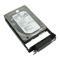
Figure 4 Drives.......................................................................................................................................................11
Figure 5 Drive Slot Numbers ..................................................................................................................................11
Figure 6 Controllers................................................................................................................................................12
Figure 7 Host Interface for FC Cable Connection (Installed in a Controller) ............................................................14
Figure 8 Host Interface for FC Cable Connections (Equipped with SFP+ Modules in All Ports and Installed in the
Controllers) ..............................................................................................................................................14
Figure 9 Host Interface for Copper Twinax Cable Connection (Installed in a Controller) .........................................15
Figure 10 iSCSI 10Gbit/s (10GBASE-T) Interface (Installed in a Controller) ...............................................................15
Figure 11 Power Supply Units...................................................................................................................................16
Figure 12 Controllers................................................................................................................................................17
Figure 13 Host Interface for FC Cable Connection (Installed in a Controller) ............................................................19
Figure 14 Host Interface for Copper Twinax Cable Connection (Installed in a Controller) .........................................19
Figure 15 iSCSI 10Gbit/s (10GBASE-T) Interface (Installed in a Controller) ...............................................................20
Figure 16 Power Supply Unit ....................................................................................................................................21
Figure 17 Front View of a Drive Enclosure ................................................................................................................22
Figure 18 Rear Views of a Drive Enclosure................................................................................................................22
Figure 19 Operation Panel (Drive Enclosure) ...........................................................................................................23
Figure 20 Drives.......................................................................................................................................................24
Figure 21 Drive Slot Numbers (Drive Enclosure).......................................................................................................24
Figure 22 I/O Module (Drive Enclosure)....................................................................................................................25
Figure 23 Power Supply Unit (Drive Enclosure) ........................................................................................................26
Figure 24 Power Distribution Unit (AC200-240V, 1U, 4 Outlets)...............................................................................27
Figure 25 Power Distribution Unit (AC200-240V, 1U, 4 Outlets)...............................................................................27
Figure 26 Power Distribution Unit (AC200-240V, 2U, 12 Outlets).............................................................................28
Figure 27 Power Distribution Unit (AC200-240V, 2U, 16 Outlets).............................................................................28
Figure 28 Power Distribution Unit (AC200-240V, 2U, 16 Outlets).............................................................................29
Figure 29 ON Position (Marked "|") of the Main Line Switches on a 1U Power Distribution Unit ..............................30
Figure 30 ON Position of the Main Line Switches on a 1U Power Distribution Unit ..................................................30
Figure 31 ON Position (Marked "|") of the Main Line Switches on a 2U Power Distribution Unit ..............................31
Figure 32 ON Position of the Main Line Switches on a 2U Power Distribution Unit ..................................................31
Figure 33 OFF Position (Marked "¡") of the Main Line Switches on a 1U Power Distribution Unit ...........................32
Figure 34 OFF Position of the Main Line Switches on a 1U Power Distribution Unit .................................................32
Figure 35 OFF Position (Marked "¡") of the Main Line Switches on a 2U Power Distribution Unit ...........................33
Figure 36 OFF Position of the Main Line Switches on a 2U Power Distribution Unit .................................................33
Figure 37 ON Position (Marked "|") of the PSU Switch on a Power Supply Unit ........................................................34
Figure 38 OFF Position (Marked "¡") of the PSU Switch of a Power Supply Unit ......................................................35
Figure 39 ETERNUS Web GUI Screen.........................................................................................................................41
Figure 40 Event Notification ....................................................................................................................................43
Figure 41 Audit Log..................................................................................................................................................44
4
FUJITSU Storage ETERNUS AF250 S2, ETERNUS AF250 All-Flash Arrays
Operation Guide (Basic)
Copyright 2019 FUJITSU LIMITED
P3AG-1842-06ENZ0
 Loading...