62 Operating Manual TX200 S5
Control and display elements Installation and operation
5.2 Control and display elements
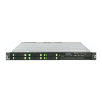
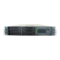
5.2.1 Front of server
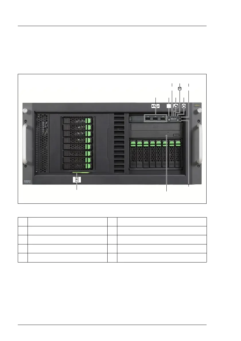
Figure 13: Front of server (example: rack model)
1 3 x USB ports 6 power-on indicator / On/Off button
2 ID indicator / ID button 7 reset button
3 CSS indicator 8 NMI button
4 Global Error indicator 9 DVD drive activity indicator
5 hard disk activity indicator 10 ID card
RST
+
CSS
ID
NMI
0
1
3
5
2
6
4
7
8
9
 Loading...