FUJITSU PSWITCH User’s Guide
70 December/2018
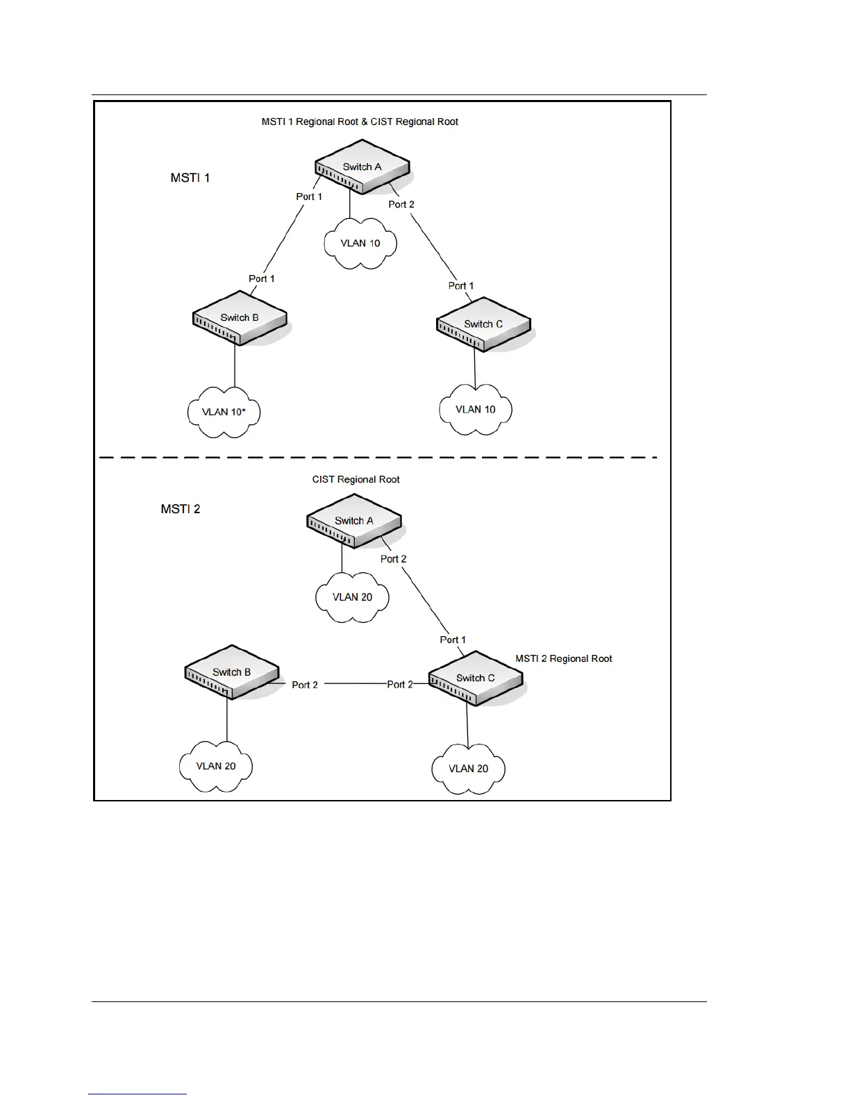
Figure 3-6: Logical MSTP Environment
For MSTP to correctly establish the different MSTIs as above, some additional
changes are required. For example, the configuration would have to be the same
on each and every bridge. That means that Switch B would have to add VLAN 10 to
its list of supported VLANs (shown in Figure 3-6 with a *). This is necessary with
MSTP to allow the formation of Regions made up of all switches that exchange the
same MST Configuration Identifier. It is within only these MST Regions that
multiple instances can exist. It will also allow the election of Regional Root Bridges