9
Before You Start
EN
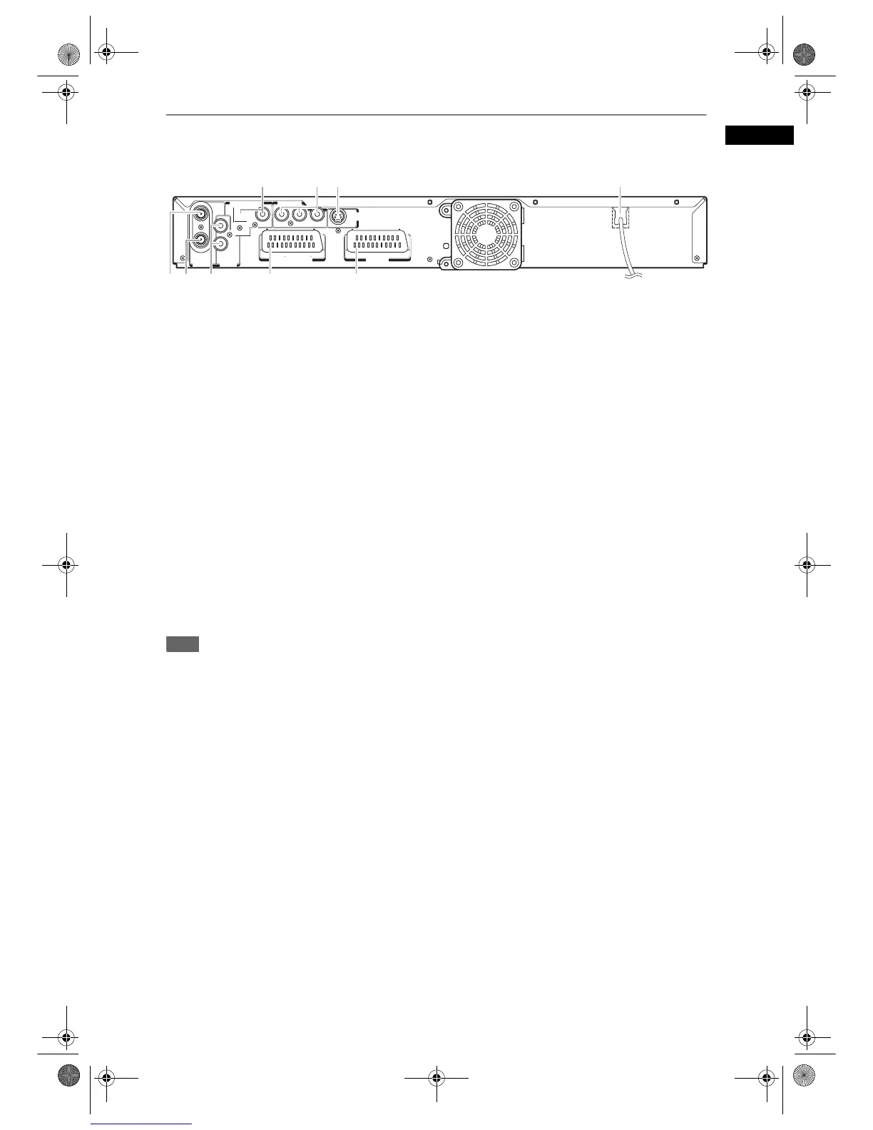
Rear Panel
1 ANTENNA IN:
Connect to an antenna cable.
2 ANTENNA OUT:
Connect to the Aerial jack on your TV, cable box
or direct broadcast system.
Use the supplied RF cable.
3 ANALOG AUDIO OUT jacks:
Connect to the audio input jacks on your TV. Use
a commercially available Audio cable.
4 AV2(DECODER):
Connect to VCR, camcorder, or other
Audio-Video equipment. Use a commercially
available Scart cable.
5AV1(TV):
Connect to the Scart jack on your TV. Use a
commercially available Scart cable.
6 Mains cable:
Connect to a standard AC outlet.
7 S-VIDEO OUT jack:
Connect to the S-Video input jack on your TV.
Use a commercially available S-Video cable.
8 COMPONENT VIDEO OUTPUT jacks:
Connect to an optional component video cable
through the component video input jacks of a TV.
9 DIGITAL AUDIO OUTPUT (OPTICAL /
COAXIAL) jacks
:
Connect to an amplifier with a digital input jack
such as a Dolby Digital decoder, DTS decoder or
MPEG decoder. Use a commercially available
Optical / Coaxial cable.
Note
• Do not touch the inner pins of the jacks on the rear panel.
Electrostatic discharge may cause permanent damage to the unit.
• This unit does not have an RF modulator.
IN
AV2
(
DECODER
)
AV1
(
TV
)
YPB/CB PR/CR
L
OUT
R
ANALOG
AUDIO OUT
IN
COAXIAL
YPB/CB PR/CR
S-VIDEO
OUT
DIGITAL AUDIO OUTPUT
PCM/BITSTREAM
COMPONENT
VIDEO OUTPUT
AV1
(
TV
)
AV2
(
DECODER
)
OPTICAL
ANTENNA
1
9
7 68
4
52 3
E2B21BD_E2B28BD_EN.book Page 9 Monday, August 21, 2006 5:05 PM