EasyManua.ls Logo

Furuno TECDIS User Manual

Furuno TECDIS
80 pages
To Next Page IconTo Next Page
Page #1 background imageLoading...
Page #1 background image
TECDIS Installation Manual Page 0
A fully type approved Electronic Chart and
Display Information System (ECDIS),
certified by DNV.
Installation Manual
Software edition: 4.7.1
Manual edition: 2.1

Table of Contents

Question and Answer IconNeed help?

Do you have a question about the Furuno TECDIS and is the answer not in the manual?

Furuno TECDIS Specifications

General IconGeneral
AIS IntegrationYes
Operating Temperature-15°C to +55°C
Chart FormatARCS
Power Supply24V DC
Data InterfacesNMEA0183, Ethernet
Radar OverlayYes
Resolution1280 x 1024 pixels
CertificationIEC

Summary

SAFETY INSTRUCTIONS

Electrical Shock and Battery Warnings

Safety warnings for electrical hazards and lithium battery.

Compass Safe Distances

Guidelines to prevent magnetic compass interference.

General Introduction to the Installation Manual

Installation and Commissioning Requirements

Procedures and personnel requirements for installation and commissioning.

System Power and Data Requirements

Specifies UPS power supply and WGS-84 datum for position inputs.

Standards Compliance

TECDIS Standards Compliance

Lists normative documents and standards met by TECDIS versions.

Equipment Lists

Standard and Optional Equipment

Lists standard and optional supply items for TECDIS.

Installation Overview

TECDIS System Wiring Diagram

Illustrates primary and secondary TECDIS system connections.

Specifications

Component Specifications

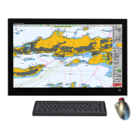
Technical details for processors and monitors.

Mouse-Trak B-MPIND-XROHS Specifications

Speaker and Alarm Interface Specifications

TELchart TA3232-1 Analog Adapter

Chapter 1: Mounting

Monitor Unit Mounting

Guidelines for selecting a mounting location for the monitor unit.

Outline Dimensions for JH 20T17 MMD

Outline Dimensions for JH 19T14 MMD

Outline Dimensions for JH 23T12 MMD

Processor Unit Mounting

Outline Dimensions for HT 405P4 TEL-A1

Control Unit Furuno RCU-018 Mounting

Furuno RCU-018 Outline (Desktop Mount)

Furuno RCU-018 Outline (Desktop Mount with Bracket)

Keyboard and Trackball Mounting

Outline Dimensions for BTC-5100C PS/2 Keyboard

Additional Units Mounting

Speaker and Alarm Interface Dimensions

Outline Dimensions for DNH HPS6 (Flush Mount)

Outline Dimensions for TA3232-1 Analog Interface Box

Outline Dimensions for MOXA OPT8F RS-422 Interface

Track Control: Anschütz NP 2025 PLUS

NAUT AW Gyro Sensor Input Requirements

Chapter 2: Wiring and Signal Distribution

RS422 Box Wiring and Isolation

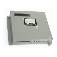
Wiring and isolation for RS422 box with 8xDB25 Female.

Wiring Diagram (HT 405P4 TEL-A1)

Signal Distribution Diagram (Internal Data Flow)

Processor Connectors (HT 405P4 TEL-A1)

Ethernet Connectors and Cable

Other Connectors

Chapter 3: Parameter Setup

3.1 Service Mode (Windows)

Procedure to exit TECDIS and enter Windows service mode.

3.2 NMEA Data Setup

Configuration of NMEA inputs, outputs, speed, and ports.

Supported NMEA Sentences

Specification

Save and Restore Setup Defaults

TECDIS NMEA and TCP/IP Server

Chart Installation / Misc

Install, Update, or Remove Chart Databases

Enter Vessel Information

Monitor Calibration and Test

Licensing

Track Control

Track Control Starting Requirements

Conditions needed to activate Track Control mode.

Track Control Default Values and Other Settings

Default route parameters and autopilot connection settings.

Route Synchronization

Replication Activation and Deactivation

Steps to activate and deactivate route replication between TECDIS units.

Chapter 4: Operational System Settings

4.1 Setup

Configuration options for ship draught, language, timezone, and NMEA.

NMEA Data Inputs

Displaying sensor input status and NMEA communication.

Operational Parameters for the Ship

Settings for own ship display and course vectors.

Operational Parameters for AIS

Chart Library

Import of S57 Data

Remove Dataset

Removing S57 chart datasets from the system.

Import of S-63 Chart Data

Chapter 5: Miscellaneous

5.1 Error Messages

List of common TECDIS error messages and their corrective measures.

Monitor Calibration

Chapter 6: Checklists Regarding Installation

6.1 Checklist Prior to Completion of TECDIS Installation

Checklist items for verifying proper TECDIS installation.

Checklist for TECDIS TCS/AW Installation

Specific checklist for TECDIS TCS and AW installation.

Sea Trial Tests

Tests to be performed during sea trials for system functionality.

Anschütz NP 2025 PLUS Autopilot Tests

Harbor acceptance and sea trial tests for the autopilot.

Track Control System Test

Items to be checked during sea trial for Track Control.

Fail to Safe Properties

Tests for fail-safe properties of the Track Control system.

Additional Checklist for TECDIS AW Installation

Extra checklist items for TECDIS AW installation.

Revision History

Revision History Summary

Overview of revisions from 1.0 to 2.1.

Contact Information

Related product manuals