ENGINE
3-19
To insert the thickness gauge under the adjust-
ing screw pad, push the pad at the bottom on
one side with a flat-blade screwdriver or a similar
tool. Insert the thickness gauge into the small
space created under the other side of the pad,
as shown in the illustration.
The thickness gauge must have a slight drag
when taking measurements.
If the thickness gauge can be moved without any
resistance, the measurement will be incorrect.
If the measurements are not within the standard
value range, adjust the value clearance by the
following procedures.
[Adjustment]
Adjust the valve clearance by loosening the lock
nut and rotating the adjusting screw so that the
thickness gauge can only be moved with a slight
drag.
After the adjustment, fold the adjusting screw in
place with a screwdriver and tighten the lock nut
to the specified torque.
Recheck the valve clearance with the thickness
gauge, and readjust if the measurements are not
within the specified value range.
<4D34>
[Inspection]
Remove the rocker cover.
Bring the No. 1 or No. 4 cylinder piston to the top
dead center (TDC) on the compression stroke
according to the following procedure:
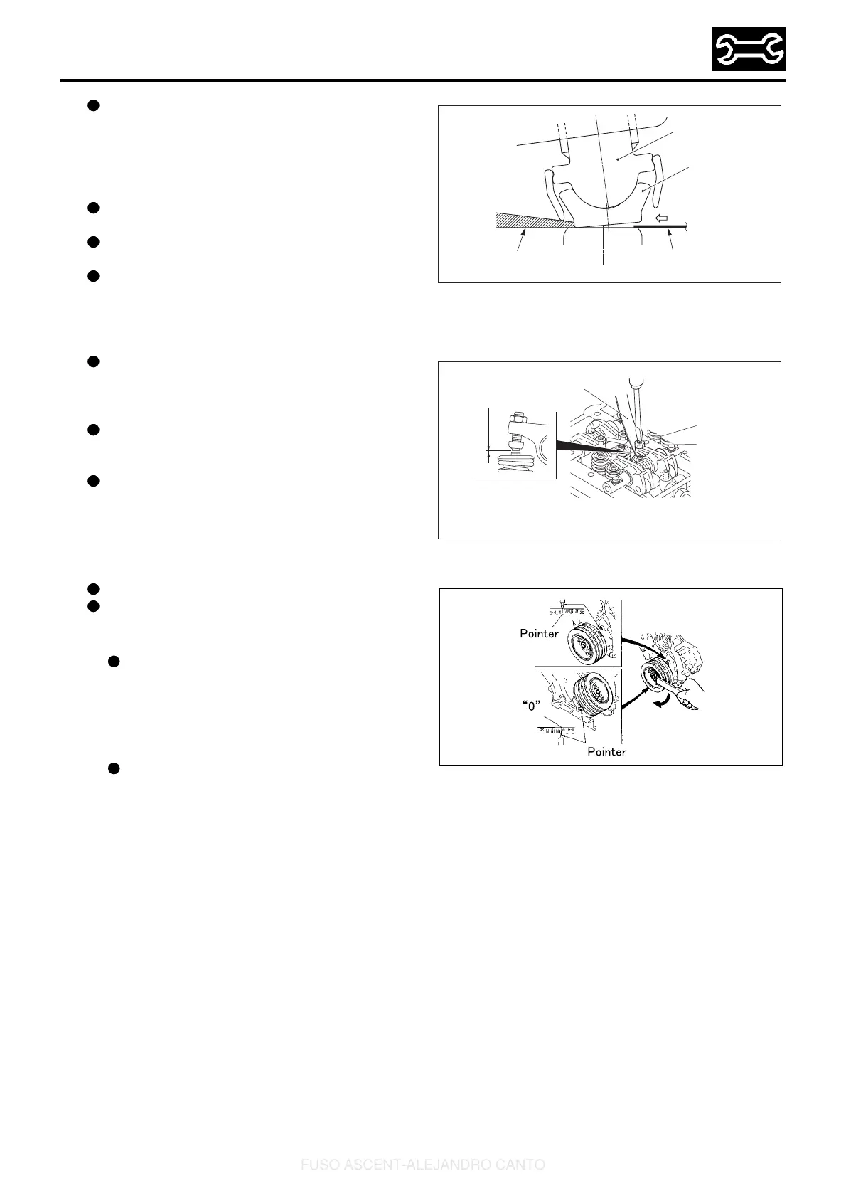
Rotate the crankshaft pulley in the illustrated
direction so that the pointer is aligned with
the “0” mark next to the “1 - 4” mark on the
inscribed scale on the crankshaft pulley.
Either one of the two pointers can be used for
this purpose.
This will place either the No. 1 or No. 4 cylin-
der piston at TDC on the compression stroke.
The cylinder in which the rocker arms for
both the intake and exhaust valves can be
pushed down by hand by the valve clearance
amounts has its piston at TDC. Rotate the
engine by one full turn to switch the TDCs of
the No. 1 and No. 4 cylinder pistons.
P30148E
Adjusting
screw
Pad
Flat-blade screwdriver
Thickness gauge
P48702E
Adjusting
screw
Lock nut
Valve clearance
Thickness gauge
49928E
FUSO ASCENT-ALEJANDRO CANTO
 Loading...