ENGINE
3-20
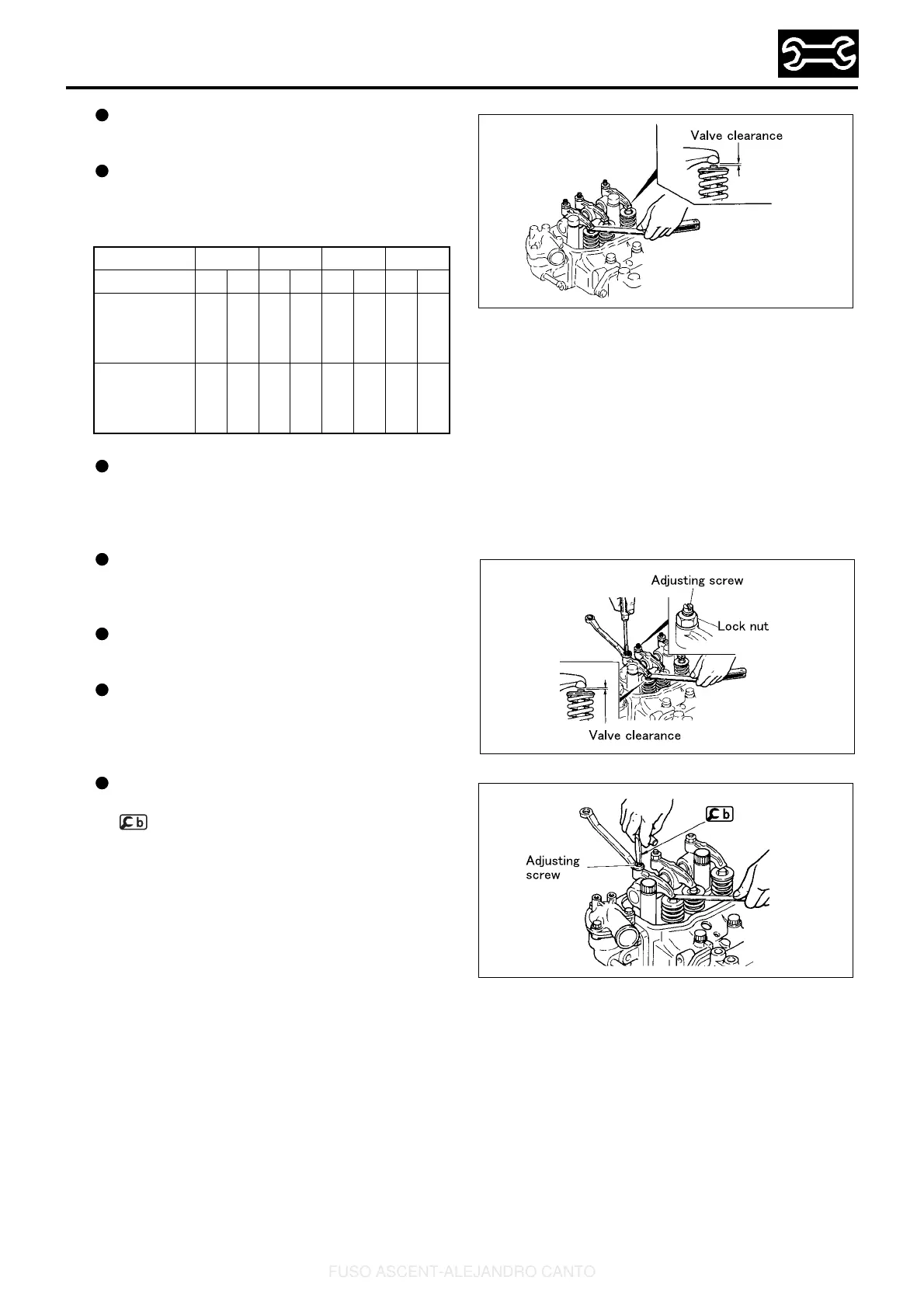
With the No. 1 or No. 4 cylinder piston at TDC,
measure the clearance of the valves marked
with a circle in the table below.
The feeler gauge must have a slight drag when
taking measurements. If the feeler gauge can be
moved without any resistance, the measurement
will be incorrect.
If the measurements are not within the standard
value range, adjust the value clearance via the
following procedures.
[Adjustment]
Adjust the valve clearance by loosening the lock
nut and rotating the adjusting screw so that the
feeler gauge can only be moved with a slight
drag.
After the adjustment, hold the adjusting screw in
position with a screwdriver and tighten the lock
nut to the specified torque.
Recheck the valve clearance with the feeler
gauge, and readjust if the measurements are not
within the specified value range.
When carrying out valve clearance adjustment
with the engine still mounted on the vehicle, use
to facilitate rotation of the adjusting screw.
Cylinder No. 1 2 3 4
Valve INEXINEXINEXINEX
No. 1 cylinder
piston at TDC
on compres-
sion stroke
OOO– –O – –
No. 4 cylinder
piston at TDC
on compres-
sion stroke
–––OO–OO
48362E
48363E
06207E
FUSO ASCENT-ALEJANDRO CANTO
 Loading...