MIC TRAC Operation Manual Model MT-3000
Copyright © 2014 Gagemaker. All rights reserved
17
Attaching Cables to the Digital Readout
Materials Needed:
¾ MIC TRAC MT-3000 base unit
¾ Force-Lok cable (only with 3000F models)
¾
¾
¾ Scale cable (attached to base unit)
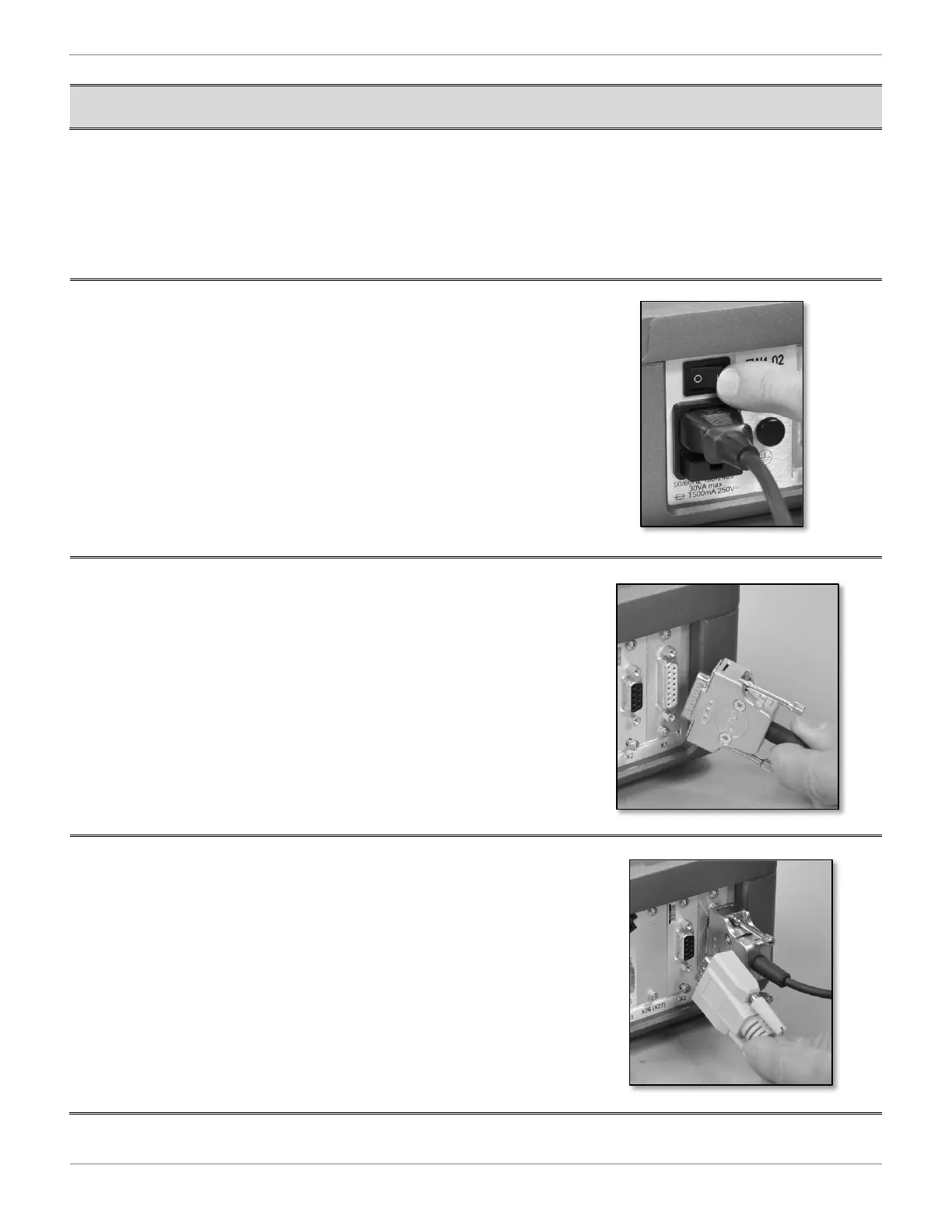
1. Ensure that the ON/OFF switch located on the rear panel
of the DRO is in the OFF position.
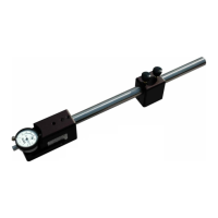
2. Plug the scale cable into the port on the rear panel of the
DRO labeled X1. Secure all connectors to the panel
using the connector screws.
Note: Do not force any electrical connections together.
Always check alignment prior to joining any
connection.
3. For the 3000F Models Only, plug the Force-Lok cable
into the X2 port on the rear panel of the DRO.