EasyManua.ls Logo

GAGEMAKER MIC TRAC MT-3000 User Manual

GAGEMAKER MIC TRAC MT-3000
36 pages
To Next Page IconTo Next Page
To Previous Page IconTo Previous Page
Page #7 background image
MIC TRAC Operation Manual Model MT-3000
Copyright © 2014 Gagemaker. All rights reserved
5
Unpacking and Handling
Before removing the unit, be sure you have a flat, secure surface to place it on. A granite or
marble surface is ideal to reduce vibration, but a good solid wood top bench with sturdy legs
is acceptable. Also, since the MIC TRAC requires an electrical power source, locate the unit
within four feet of an electrical outlet.
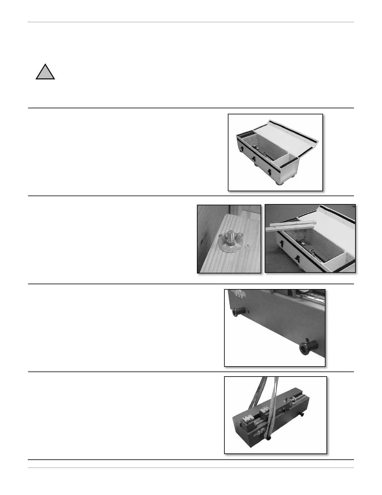
1. After opening the cover of the shipping carton,
check for signs of damage.
Note: If the unit appears damaged, contact
Gagemaker immediately at 713-472-7360.
2. To release the unit from the shipping carton,
loosen and remove the wing nuts and washers.
3. Remove the wood strips. The unit is ready to
be lifted from the shipping carton.
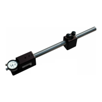
4. For removing the unit, there are four lifting lugs
attached to the sides of the MIC TRAC.
5. Secure two 36" X ¾" durable lifting
straps around the lifting lugs on each
side.
!

Other manuals for GAGEMAKER MIC TRAC MT-3000

Questions and Answers:

GAGEMAKER MIC TRAC MT-3000 Specifications

General IconGeneral
BrandGAGEMAKER
ModelMIC TRAC MT-3000
CategoryMeasuring Instruments
LanguageEnglish

Summary

Introduction to MIC TRAC

What is the MIC TRAC?

Defines the MIC TRAC as an electronic calibration and measurement center for part inspection and gage calibration, detailing its capabilities.

Gagemaker's Philosophy of Accuracy

Explains Gagemaker's perspective on accuracy, emphasizing environmental factors like temperature and humidity.

Technical Support

Provides contact details including phone number and operating hours for Gagemaker customer support.

Product Information and Updates

Directs users to the Gagemaker website for obtaining the latest product information and software updates.

Unpacking and Handling MIC TRAC

Returning the MIC TRAC

MIC TRAC Parts List

MIC TRAC Part Descriptions

Details and illustrates specific components of the MIC TRAC, covering parts like receiver pads and adjustment knobs.

Digital Readout (DRO) Front Panel

Digital Readout (DRO) Rear Panel

Digital Readout (DRO) Screen Features

Main Screen Layout Overview

Describes the primary components of the DRO screen, including the status bar, position display, and message line.

Softkey Functionality

Explains the operation and functions of the DRO's softkeys across different pages for user interaction.

Setup Procedures

Removing Lifting Lugs (Optional)

Provides step-by-step instructions for removing and replacing lifting lugs on the MIC TRAC unit.

Attaching Cables to the Digital Readout

Mounting the Flat Face Anvils (TF-1F Blocks)

Connecting an Optional Printer

Zeroing the MIC TRAC (Without Force-Lok)

Zeroing the MIC TRAC (With Force-Lok)

Changing MIC TRAC Force-Lok Measuring Force

Changing Internal to External Measurement Mode

Changing the Zero Setting

Operating Procedures

Measuring Parts with Force-Lok

Guides users on the correct method for measuring parts using the MIC TRAC with the Force-Lok feature engaged.

Troubleshooting Guide

Care and Maintenance

Maintenance Tips

Offers essential tips for maintaining the MIC TRAC, including lubrication, proper usage surfaces, and environmental care.

Maintenance Note

Clarifies that the unit has no user-serviceable parts and outlines requirements for calibration and proper shipping.

Safety Tips

Details crucial safety precautions for operating the MIC TRAC, covering cable management and personal safety.

Warranty Information

Products Requiring Repair or Calibration Return Process

Explains the process for returning the MIC TRAC for repair or calibration, including obtaining authorization.

Technical Information

Related product manuals