Model 560XL Appendix – Systems Description
Textron Aviation Citation 560XL 190-02313-03 Rev. 8
A-14
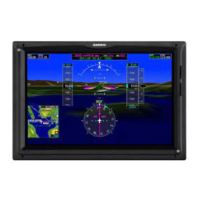
G5000 Flight Instruments
Flight instruments are an integrated part of the G5000 system. For system descriptions, operating
instructions, and abnormal failure indication refer to the Cockpit Reference and Pilot’s Guides.
Engine Instrumentation
Engine instruments are normally located in a window on the left side of the MFD. They are grouped
according to their function. At the top, the N
1
% gauge (fan speed) is used to set power while observing
ITT and other engine limits. N
1
% and ITT are displayed in gauge and pointer formats, with a digital
numeric display at the bottom of the gauge. All other engine parameters are displayed with a digital
numeric display. These include N
2
% (turbine speed), oil pressure and temperature, fuel flow, and fuel
quantity and temperature.
The engine transducers send their signals to the Garmin GEAs (Engine and Airframe LRU) which process
the signals and allow the engine parameters to be displayed on the MFD. Two GEAs are installed to
provide independent display of parameters for each engine. The GEA circuit breakers are located on the
LH and RH circuit breaker panels in the ENGINE INSTRUMENTS group and are labeled L & R GEA
(PRIM) and L & R GEA (SEC).
The N
1
tachometer is displayed in percent RPM. The pointer and digital display of N
1
are always
displayed. Resolution of the digital display is 0.1%.
The ITT indicator gives an indication of inter-turbine temperature in °C. The pointer and digital display of
ITT are always displayed. Exceedance conditions are determined based on the Airplane Flight Manual
engine ITT limitations for engine start, or conditions except start, as appropriate. The range of the amber
caution band will change depending if the engine is running or not; the specific marking ranges are
described in Section 2 of this flight manual. Resolution of the digital display is 1° C.
The N
2
tachometer is displayed in percent RPM. Resolution of the digital display is 0.1%.
The oil pressure indicator displays oil pressure in PSI. Exceedance conditions are determined based on
engine N
2
speed and transient time limits. See Section 2 of this Airplane Flight Manual Supplement for
additional details. Resolution of the digital display is 1 PSI.
The oil temperature indicator displays oil temperature in °C. Exceedance conditions are determined
based on transient time limits. See Section 2 of this Airplane Flight Manual Supplement for additional
details. Resolution of the digital display is 1 °C.
The fuel quantity indicators give an indication of fuel quantity contained in the left and right tank. There is
also a digital display of total fuel quantity value which is a sum of the left and right quantities. The units of
fuel can be configured by appropriate maintenance personnel to be pounds or kilograms of fuel.
Resolution of left, right, and total fuel quantity are 10 LB or 5 KG.
The fuel flow indicators give an indication of fuel consumption of the left and right engine. The units of
can be configured by appropriate maintenance personnel to be pounds/hour or kilograms/hour of fuel.
Resolution of the digital display is 10 LB/HOUR or 5 KG/HOUR.
The fuel temperature indicator displays fuel temperature in °C. It is the responsibility of the crew to
adhere to fuel temperature limitations provided in the flight manual based on the type of fuel used.
Resolution of the digital display is 1 °C.








 To Next Page