Model 560XL Appendix – Systems Description
190-02313-03 Rev. 8 Textron Aviation Citation 560XL
A-17
clear that terrain or obstacle. If the FPM is above that terrain or obstacle, the aircraft will clear the terrain
or obstacle IF, AND ONLY IF, THE CURRENT AIRCRAFT CONFIGURATION AND THE AIRCRAFT
PERFORMANCE WILL PERMIT YOU TO MAINTAIN THE CURRENT VERTICAL (CLIMB) GRADIENT
UNTIL PAST THE TERRAIN OR OBSTACLE.
Traffic
If traffic that is within the SVT field of view is detected by the G5000 system, a
symbol will be displayed on the PFD indicating the direction and relative
altitude of the traffic. The traffic symbol size will increase as the traffic gets
closer to give the pilot a sense of relative distance to the threat aircraft.
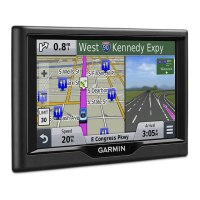
HORIZON LINE and HEADING
The SVT display includes an always visible white horizon line that represents
the true horizon. Terrain will be presented behind the horizon line. Terrain
shown above the horizon line is above the current aircraft altitude. Terrain
that is shown below the horizon line is below the aircraft altitude.
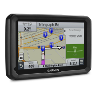
A heading scale may be displayed on the PFD horizon line, if Horizon
Heading is selected by the pilot. The heading marks are spaced in even 30
degree increments and are presented just above the horizon line with tic
marks that intersect the horizon line. The horizon heading will correspond to that presented by the HSI.
Because the horizon heading is only displayed in 30 degree increments, it should only be used for
general heading awareness and not be used to establish the aircraft heading.
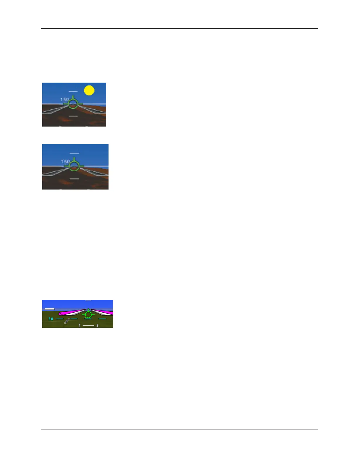
Airport Signs and Runway Highlight
If Airport Signs is selected, a “sign post” along with a representation of the runways will be plotted on the
SVT display for nearby airports that are contained in the G5000 airport database. The signpost will
become visible when you are within approximately 15 NM of the airport. If an approach to a specific
runway has been loaded and activated, that runway will be highlighted on the SVT display.
When on an approach, the highlight for the approach runway will be considerably larger than “normal” to
assist in visually acquiring the runway. The oversized highlight will automatically shrink around the
runway depiction so that the runway is proportionally displayed when the aircraft is within approximately
½ NM of the threshold. Runway highlighting is displayed even if Airport Signs are turned off.
FPA Reference
A flight path angle reference may be displayed on the PFD when the flight
path marker is displayed. The flight path angle reference may be set
manually or, when set to AUTO, the flight path angle for the approach
loaded in the flight plan is automatically set.
DR / LOI FMS Modes
When both GPS/SBAS receivers are inoperative or GPS navigation information is not available or
invalid, the G5000 system will enter one of two modes: Dead Reckoning mode (DR) or Loss Of
Integrity mode (LOI). DR mode will become active when over 30 NM from the destination airport.
When less than 30 NM from the destination airport, LOI mode will become active.
In Loss of Integrity mode, revert to an alternate means of navigation appropriate to the route and
phase of flight.
In Dead Reckoning mode, the navigation Maps will continue to be displayed with a ghosted ownship
symbol and an amber ‘DR’ overwriting the ownship symbol. Aircraft position will be based upon the
last valid GPS position and estimated by Dead Reckoning methods. Changes in wind speed and/or
wind direction affect the estimated position substantially. Dead Reckoning is only available in
 Loading...