Model 560XL Appendix – Systems Description
Textron Aviation Citation 560XL 190-02313-03 Rev. 8
A-16
Synthetic Vision
See the G5000 Pilot’s Guide 190-02537-02 for more detailed information regarding the synthetic vision
system.
General
The Synthetic Vision Technology (SVT) sub system is dependent upon terrain data provided by the
underlying G5000 system. If, for some reason, the terrain data is not available from the G5000, all of the
components of the SVT will be unavailable. The flight path marker, flight path angle reference, horizon
heading, and airport signs are all sub-components of the Synthetic Terrain display. Those features are
selected or de-selected using the PFD softkeys on the PFD Settings, Attitude Overlays menu.
Synthetic Terrain
The Terrain/Obstacle/Airport databases have an area of coverage as detailed below:
The Terrain Database has an area of coverage from North 89° Latitude to South 89° Latitude in
all longitudes.
The Obstacle Database coverage area includes the United States, Europe, and Canada.
NOTE
The area of coverage may be modified, as additional terrain data sources become
available.
Obstacle And Terrain Alerts And Warnings
Obstacles and terrain displayed on the SVT may be highlighted if an alert or warning is generated by the
G5000 TAWS system. As the aircraft approaches an obstacle or terrain, its relative size will increase to
give the pilot a sense of proximity and closure rate to the obstacle or terrain. If an obstacle alert is
presented for an obstacle that is in the SVT field of view, the obstacle symbol on the PFD will turn yellow
in color. If an obstacle warning is generated by the G5000 system, the obstacle symbol on the PFD will
turn red.
If the G5000 TAWS system generates a terrain alert or warning, the terrain feature displayed on the PFD
will be colored yellow for an alert or red for a warning for as long as the alert remains valid.
Because the area monitored by the TAWS system can be wider than the field of view that can be
displayed by the SVT, it is possible to receive an obstacle or terrain audible alert for an obstacle or terrain
that is not shown on the SVT display. In those cases, the object generating the alert will be left or right
of the aircraft. Refer to the other displays in the aircraft to determine the cause of the message.
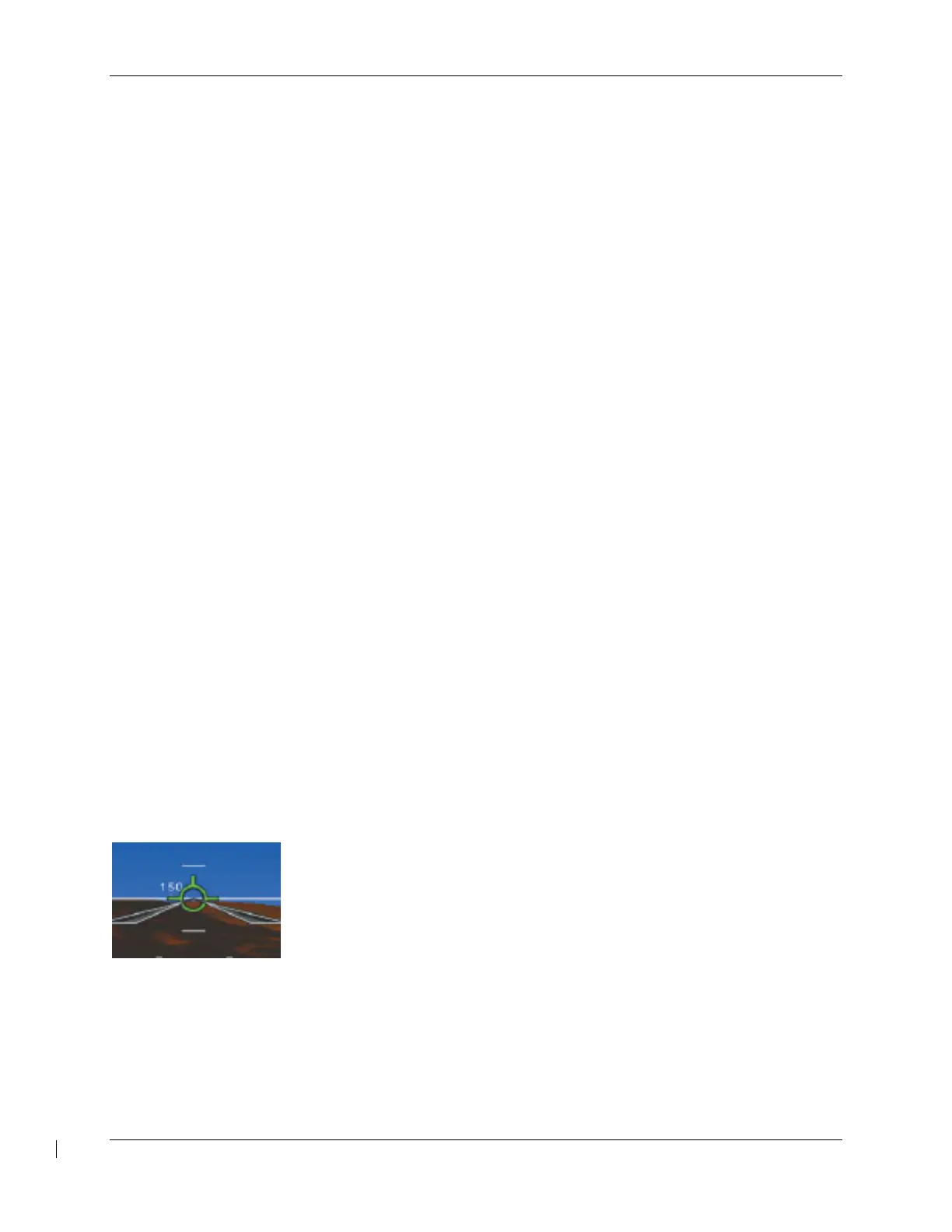
Flight Path Marker
The SVT display includes a green circular barbed symbol called the Flight Path
Marker (FPM) that represents the current path of the airplane relative to the
terrain display. The FPM is always displayed when synthetic terrain is
displayed and the aircraft ground speed exceeds 30 KT. The FPM indicates
the current lateral and vertical path of the airplane as determined by the AHRS
and GPS sensor. If the FPM is above the horizon line, the airplane is
climbing, and similarly if the FPM is below the horizon line, the airplane is
descending. If the airplane is flying in a crosswind, the FPM will be offset from the center of the display.
In that case, the center of the PFD airplane reference symbol indicates the airplane heading and the FPM
indicates the direction that the airplane is actually moving, taking into account the crosswind.
The FPM indicates the current path of the airplane but does not predict the future path. If aircraft
attitude, power setting, airspeed, crosswind, etc. are changed, the FPM will move to indicate the new path
resulting from those changes.
If the FPM is below the terrain or obstacle displayed behind it on the PFD, the current aircraft path will not