Electronic Head Assembly
03/07/03
3-3
Connectors
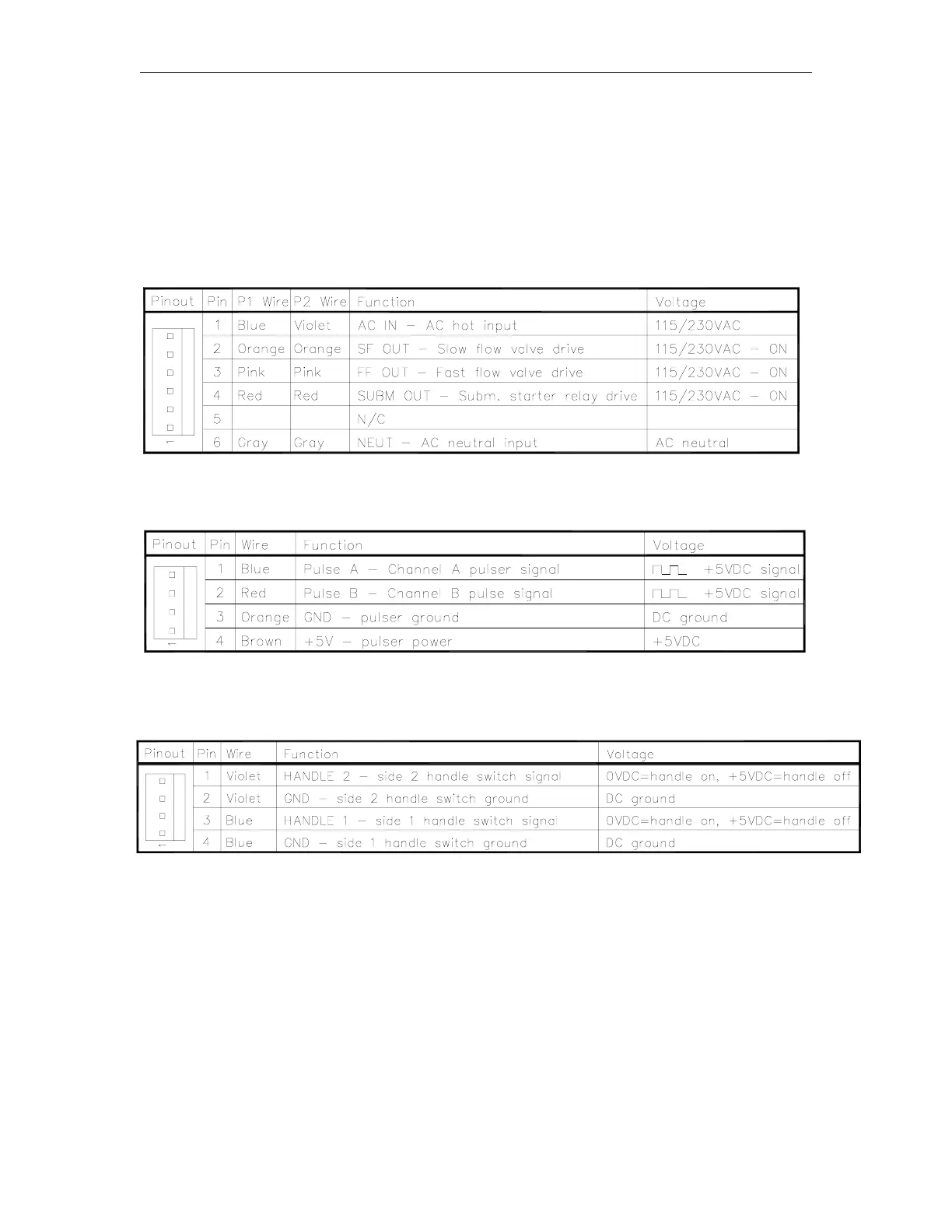
Connector P1 controls side 1 and P2 controls side 2. The AC IN and NEUT pins are used as a
pump authorization signal when SW1-6 is closed. The AC IN also feeds the SF, FF, and SUBM
relays. The SF and FF outputs can directly power the solenoid valves. The SUBM output can
power a customer-supplied submersible starter relay. The starter relay’s coil current must not
exceed 300 mA.
P1 and P2 - AC Input, Valve, and Submersible Relay Outputs
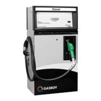
P3 - Side 1 Pulser Input, P5 - Side 2 Pulser Input
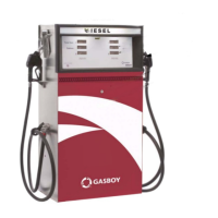
P4 - Handle Switch Inputs
NOTE: Pin 2 and Pin 4 are not used on the Front Load option.