EasyManua.ls Logo

GATEXPERT SL500DCL - Terminal Instructions; Wiring to Terminals

GATEXPERT SL500DCL
53 pages
Print Icon
To Next Page IconTo Next Page
To Previous Page IconTo Previous Page
Loading...
Instructions for SL500DCL/SL800DCL
www.gatexpertstore.com
15
Insert the wire into the
number on the terminal that
you are looking to connect to.
Refer to Page 14.
Tighten with a screwdriver
to secure the wire in place.
Terminal Instructions
All changes to these settings below must be completed by licensed electrician.
Wiring to the Terminal
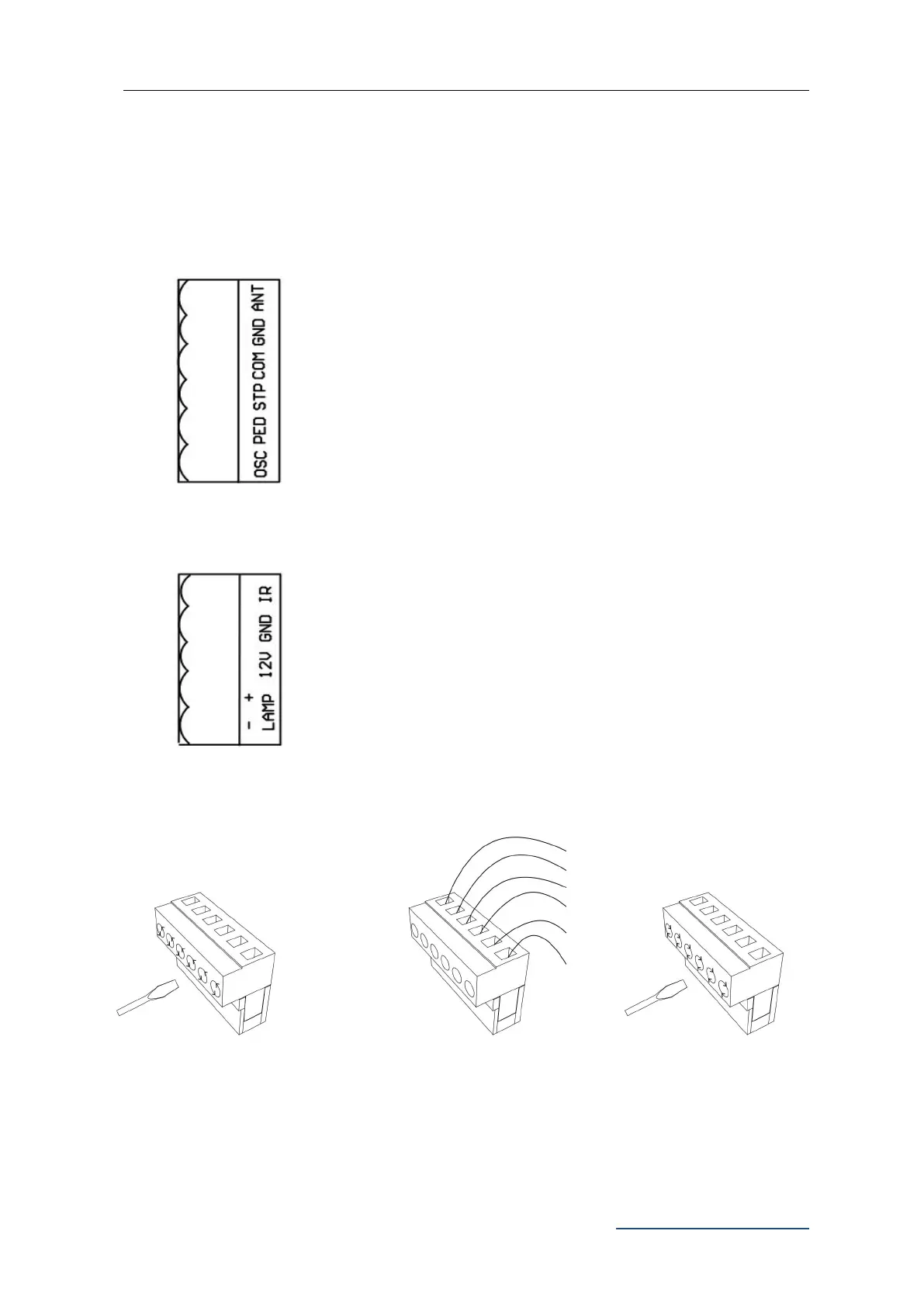
X7 Terminal: (as per Figure 20):
ANT: Extra Antenna
GND: Extra Antenna Shield
COM: Common Terminal for External Push Button
STP: External Stop Push Button Switch
PED: External Close Push Button Switch
OSC: External Open Push Button Switch
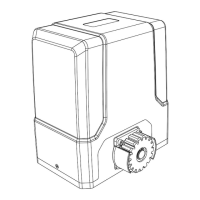
X5 Terminal:
IR: Photocell Input Common Terminal for Photocell(N.C.)
GND: Ground
12V: Additional Accessories +12VDC, after gate closed in place,
the board will enter into low power consumption mode, this
terminal will cut off the 12V power supply.
LAMP+: Alarm Lamp +12/24VDC
LAMP-: Alarm Lamp -12/24VDC
Using a screwdriver to
loosen the screw on the
side of the terminal.

Related product manuals