Installation
2.16 QS4 Technical Reference Manual
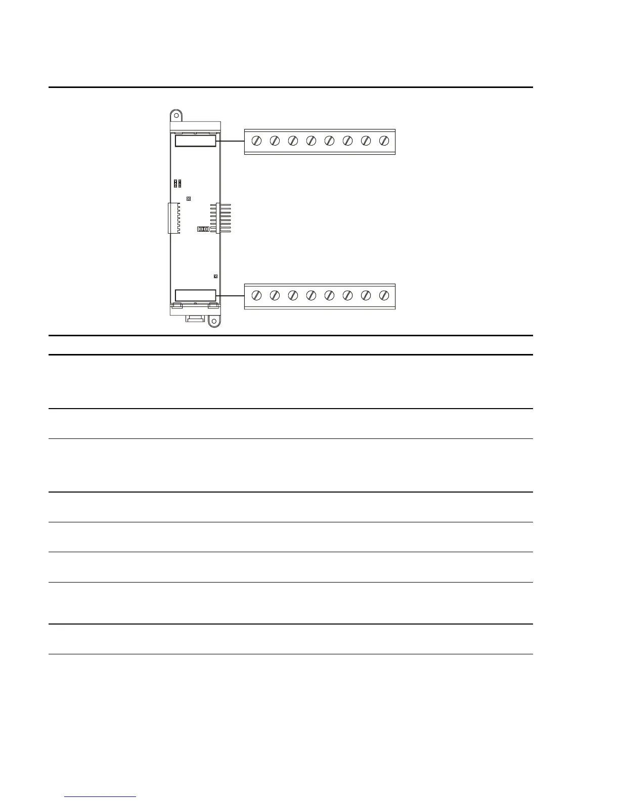
Table 2-2: SLIC Signature Loop Intelligent Controller card
18765432
TB1
B+ B– A+ A– B+ B– A+ A–
NAC 1 NAC 2
+
–
+
–
A+ A– B+ B–
OUT LOOPIN
18765432
TB2
Terminal No. Name Description
TB–1, –2 NAC 1 B+, B– Connects to the IN +/– terminals of the first device on the
NAC circuit. Polarity markings (+/–) indicate output signal
polarity with the circuit turned off. Polarity reverses with the
circuit turned on.
TB–3, –4 NAC 1 A+, A– Connects to the OUT +/– terminals of the last device on the
NAC circuit. Class A configuration only.
TB–5, –6 NAC 2 B+, B– Connects to the IN +/– terminals of the first device on the
NAC circuit. Polarity markings (+/–) indicate output signal
polarity with the circuit turned off. Polarity reverses with the
circuit turned on.
TB–7, –8 NAC 2 A+, A–
Connects to the OUT +/– terminals of the last device on the
NAC circuit. Class A configuration only.
TB2–1, –2 OUT+, OUT–
Connects to the next device on the same 24VDC riser used
to provide 24 Vdc to NAC 1 and NAC 2.
TB2–3, –4 IN+, IN–
Connects to the signal source used to provide 24 Vdc to
NAC 1 and NAC 2.
TB2–5, –6 LOOP A+, A– Connects to the DATA OUT +/– terminals of last device on
the Signature signaling line circuit. Class A configuration
only.
TB2–7, –8 LOOP B+, B– Connects to the DATA IN +/– terminals of the first device on
the Signature signaling line circuit.
Technical Manuals Online! - http://www.tech-man.com