Installation
QS4 Technical Reference Manual 2.17
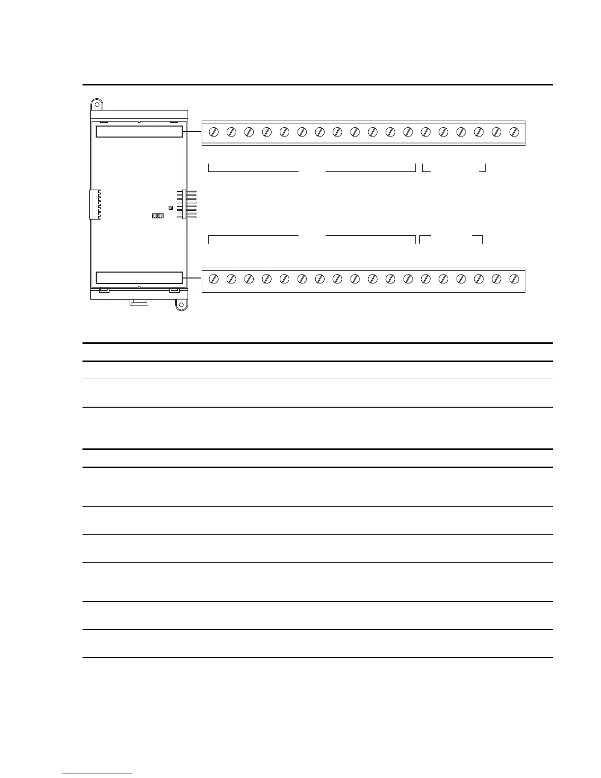
Table 2-3: ZA8–2 terminal definitions
B+ B– A+ A–
ZONE 1
1 18171615141312111098765432
B+ B– A+ A–
ZONE 2
B+ B– A+ A–
ZONE 3
B+ B– A+ A–
ZONE 4
IN+ IN–
NAC PWR
TB1
B+ B– A+ A–
ZONE 5
B+ B– A+ A–
ZONE 6
B+ B– A+ A–
ZONE 7
B+ B– A+ A–
ZONE 8
IN+ IN–
NAC PWR
TB2
1 18171615141312111098765432
IDC
IDC
IDC/NAC
IDC/NAC
IDC circuit connections
Terminal No. Name Description
TB1–1, –2 ZONE 1 B+, B– Connects to the IN +/– terminals of the first device on the IDC.
TB1–3, –4 ZONE 1 A+, A–
Connects to the OUT +/– terminals of the last device on the
IDC.
Note: ZONE 2, 3, 5, 6, and 7 connect the same as described for ZONE 1.
IDC/NAC circuit connections
Terminal No. Name Description
TB1–13, –14 ZONE 4 B+, B–
Connects to the IN +/– terminals of the first device on the NAC.
Polarity markings (+/–) indicate output signal polarity with the
circuit turned off. Polarity reverses with the circuit turned on.
TB1–15, –16 ZONE 4 A+, A– Connects to the OUT +/– terminals of the last device on the
NAC.
TB1–17, –18 NAC PWR IN+, IN–
Connects to the signal source used to provide 24VDC to ZONE
4.
TB2–13, –14 ZONE 8 B+, B– Connects to the IN +/– terminals of the first device on the NAC.
Polarity markings (+/–) indicate output signal polarity with the
circuit turned off. Polarity reverses with the circuit turned on.
TB2–15, –16 ZONE 8 A+, A– Connects to the OUT +/– terminals of the last device on the
NAC.
TB2–17, –18 NAC PWR IN+, IN–
Connects to the signal source used to provide 24VDC to ZONE
8.
Note: ZONE 4 and ZONE 8 may be programmed as IDC circuits.
Technical Manuals Online! - http://www.tech-man.com