GE Multilin 239 Motor Protection Relay 8-5
8 TESTING 8 TESTING
8
8.6 GROUND CURRENT ACCURACY
1. Alter the following setpoints:
66<67(06(783?&7,13876?*5281'6(16,1*;
66<67(06(783?&7,13876?*5281'&735,0$5<
63527(&7,21?*5281'&855(17?*5281'75, 32))
63527(&7,21?*5281'&855(17?*5281'$/$5 02))
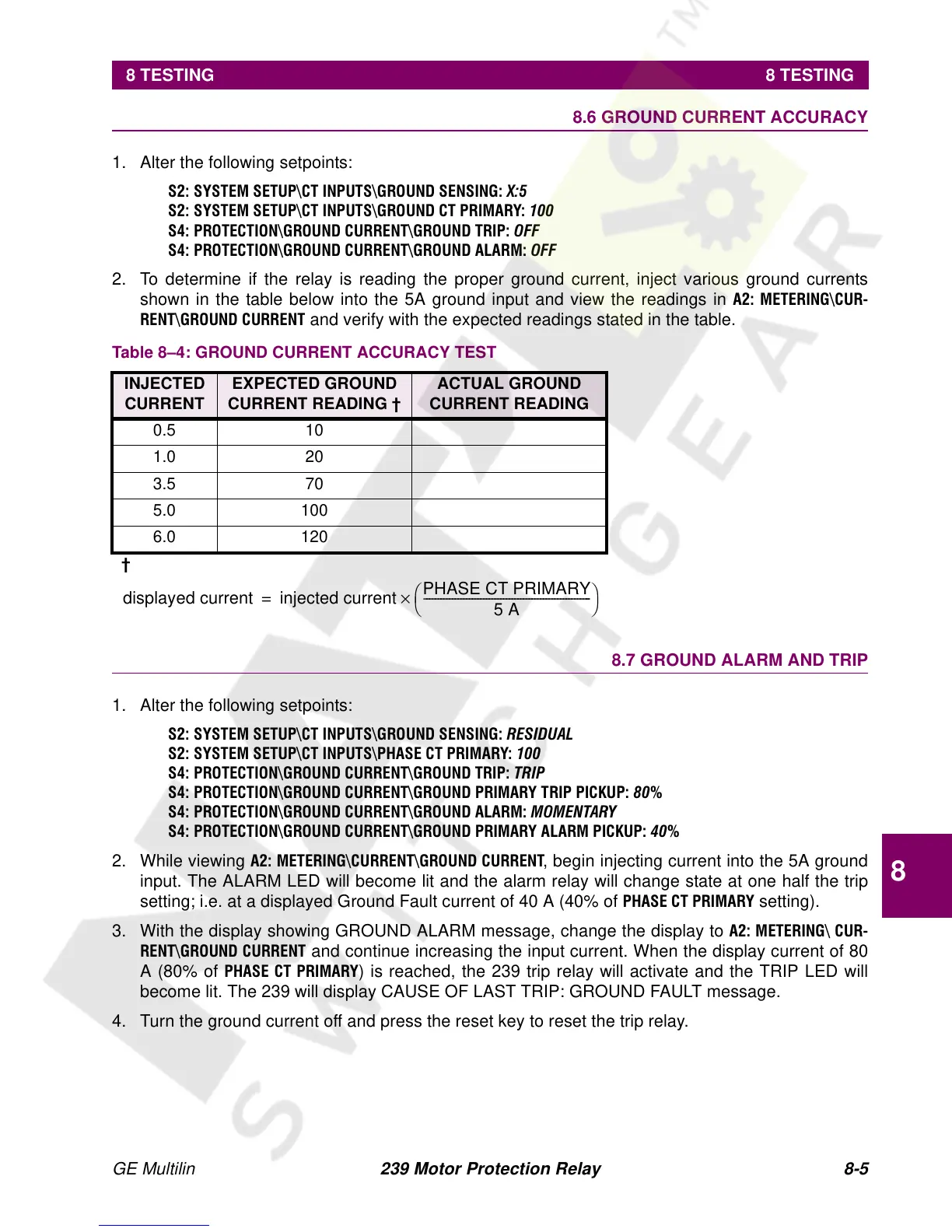
2. To determine if the relay is reading the proper ground current, inject various ground currents
shown in the table below into the 5A ground input and view the readings in
$ 0(7(5,1*?&85
5(17?*5281'&855(17
and verify with the expected readings stated in the table.
8.7 GROUND ALARM AND TRIP
1. Alter the following setpoints:
66<67(06(783?&7,13876?*5281'6(16,1*5(6,'8$/
66<67(06(783?&7,13876?3+$6(&735,0$5<
63527(&7,21?*5281'&855(17?*5281'75, 375,3
63527(&7,21?*5281'&855(17?*5281'3 5,0$5<75,33,&.83
63527(&7,21?*5281'&855(17?*5281'$/$5 0020(17$5<
63527(&7,21?*5281'&855(17?*5281'3 5,0$5<$/$503,&.83
2. While viewing $0(7 (5,1*?&855( 17?*528 1' &855 (17, begin injecting current into the 5A ground
input. The ALARM LED will become lit and the alarm relay will change state at one half the trip
setting; i.e. at a displayed Ground Fault current of 40 A (40% of
3+$6(&735,0$5< setting).
3. With the display showing GROUND ALARM message, change the display to
$0 (7(5,1*? &85
5(17?*5281' &855(17
and continue increasing the input current. When the display current of 80
A (80% of
3+$6( &7 35,0$5<) is reached, the 239 trip relay will activate and the TRIP LED will
become lit. The 239 will display CAUSE OF LAST TRIP: GROUND FAULT message.
4. Turn the ground current off and press the reset key to reset the trip relay.
Table 8–4: GROUND CURRENT ACCURACY TEST
INJECTED
CURRENT
EXPECTED GROUND
CURRENT READING †
ACTUAL GROUND
CURRENT READING
0.5 10
1.0 20
3.5 70
5.0 100
6.0 120
†
displayed current injected current
PHASE CT PRIMARY
5 A
-----------------------------------------------------------
×
=