GE Multilin 239 Motor Protection Relay 3-1
3 OPERATION 3 OPERATION
3
239 INSTRUCTION MANUAL 3 OPERATION 3.1 FRONT PANEL
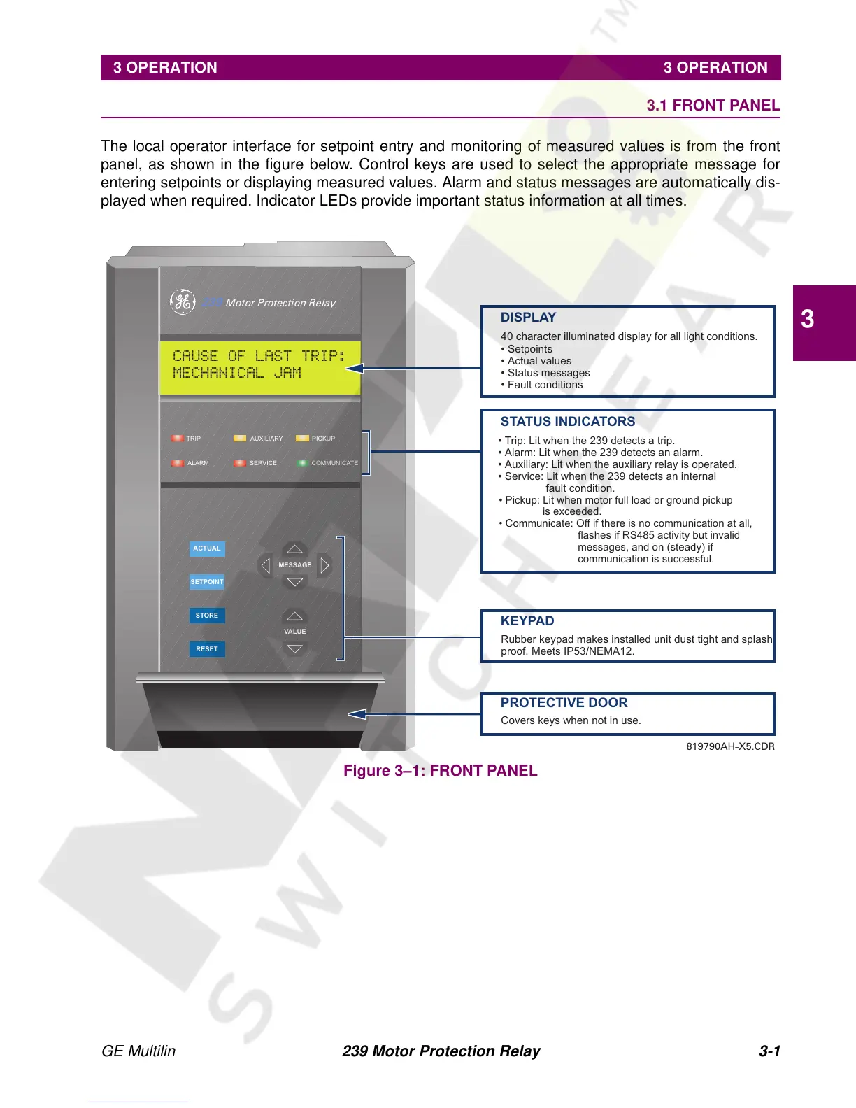
The local operator interface for setpoint entry and monitoring of measured values is from the front
panel, as shown in the figure below. Control keys are used to select the appropriate message for
entering setpoints or displaying measured values. Alarm and status messages are automatically dis-
played when required. Indicator LEDs provide important status information at all times.
Figure 3–1: FRONT PANEL
TRIP
ALARM
AUXILIARY
SERVICE
PICKUP
COMMUNICATE
RESET
STORE
ACTUAL
VALUE
MESSAGE
SETPOINT
DISPLAY
40 character illuminated display for all light conditions.
• Setpoints
• Actual values
• Status messages
• Fault conditions
STATUS INDICATORS
• Trip: Lit when the 239 detects a trip.
• Alarm: Lit when the 239 detects an alarm.
• Auxiliary: Lit when the auxiliary relay is operated.
• Service: Lit when the 239 detects an internal
fault condition.
• Pickup: Lit when motor full load or ground
is exceeded.
• Communicate: Off if there is no communication at all,
flashes if RS485 activity but invalid
messages, and on (steady) if
communication is successful.
pickup
KEYPAD
Rubber keypad makes installed unit dust tight and splash
proof. Meets IP53/NEMA12.
PROTECTIVE DOOR
Covers keys when not in use.
239 Motor Protection Relay
CAUSE OF LAST TRIP:
MECHANICAL JAM
819790AH-X5.CDR