5-6 239 Motor Protection Relay GE Multilin
5 MONITORING 5 MONITORING
5
5.3 A2: METERING
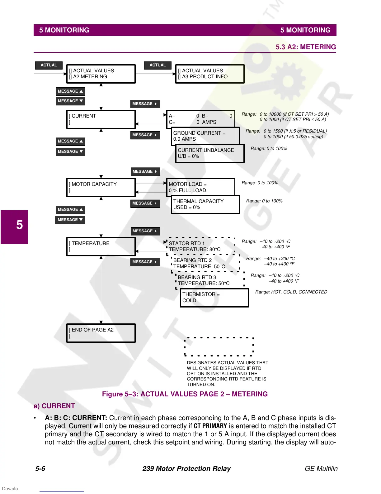
Figure 5–3: ACTUAL VALUES PAGE 2 – METERING
a) CURRENT
• A: B: C: CURRENT: Current in each phase corresponding to the A, B and C phase inputs is dis-
played. Current will only be measured correctly if
&735,0$5< is entered to match the installed CT
primary and the CT secondary is wired to match the 1 or 5 A input. If the displayed current does
not match the actual current, check this setpoint and wiring. During starting, the display will auto-
]] ACTUAL VALUES
]] A2 METERING
ACTUAL
MESSAGE
▼
] CURRENT
]
MESSAGE
▲
A= 0 B= 0
C= 0 AMPS
GROUND CURRENT =
0.0 AMPS
CURRENT UNBALANCE
U/B = 0%
] MOTOR CAPACITY
]
MOTOR LOAD =
0 % FULL LOAD
THERMAL CAPACITY
USED = 0%
]] ACTUAL VALUES
]] A3 PRODUCT INFO
ACTUAL
Range: 0 to 10000 (if CT SET PRI > 50 A)
0 to 1000 (if CT SET PRI
≤
50 A)
Range: 0 to 100%
MESSAGE
▲
MESSAGE
▲
MESSAGE
▼
MESSAGE
▼
MESSAGE
4
MESSAGE
4
MESSAGE
4
MESSAGE
3
MESSAGE
3
STATOR RTD 1
TEMPERATURE: 80°C
BEARING RTD 2
TEMPERATURE: 50°C
BEARING RTD 3
TEMPERATURE: 50°C
THERMISTOR =
COLD
] TEMPERATURE
]
Range: –40 to +200 °C
–40 to +400 °F
Range: HOT, COLD, CONNECTED
DESIGNATES ACTUAL VALUES THAT
WILL ONLY BE DISPLAYED IF RTD
OPTION IS INSTALLED AND THE
CORRESPONDING RTD FEATURE IS
TURNED ON.
] END OF PAGE A2
]
MESSAGE
3
Range: 0 to 1500 (if X:5 or RESIDUAL)
0 to 1000 (if 50:0.025 setting)
Range: 0 to 100%
Range: 0 to 100%
Range: –40 to +200 °C
–40 to +400 °F
Range: –40 to +200 °C
–40 to +400 °F