GE Multilin 239 Motor Protection Relay 2-3
2 INSTALLATION 2 INSTALLATION
2
2.3 EXTERNAL CONNECTIONS
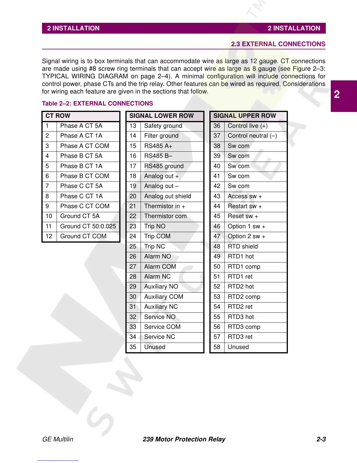
Signal wiring is to box terminals that can accommodate wire as large as 12 gauge. CT connections
are made using #8 screw ring terminals that can accept wire as large as 8 gauge (see Figure 2–3:
TYPICAL WIRING DIAGRAM on page 2–4). A minimal configuration will include connections for
control power, phase CTs and the trip relay. Other features can be wired as required. Considerations
for wiring each feature are given in the sections that follow.
Table 2–2: EXTERNAL CONNECTIONS
CT ROW SIGNAL LOWER ROW SIGNAL UPPER ROW
1 Phase A CT 5A 13 Safety ground 36 Control live (+)
2 Phase A CT 1A 14 Filter ground 37 Control neutral (–)
3 Phase A CT COM 15 RS485 A+ 38 Sw com
4 Phase B CT 5A 16 RS485 B– 39 Sw com
5 Phase B CT 1A 17 RS485 ground 40 Sw com
6 Phase B CT COM 18 Analog out + 41 Sw com
7 Phase C CT 5A 19 Analog out – 42 Sw com
8 Phase C CT 1A 20 Analog out shield 43 Access sw +
9 Phase C CT COM 21 Thermistor in + 44 Restart sw +
10 Ground CT 5A 22 Thermistor com 45 Reset sw +
11 Ground CT 50:0.025 23 Trip NO 46 Option 1 sw +
12 Ground CT COM 24 Trip COM 47 Option 2 sw +
25 Trip NC 48 RTD shield
26 Alarm NO 49 RTD1 hot
27 Alarm COM 50 RTD1 comp
28 Alarm NC 51 RTD1 ret
29 Auxiliary NO 52 RTD2 hot
30 Auxiliary COM 53 RTD2 comp
31 Auxiliary NC 54 RTD2 ret
32 Service NO 55 RTD3 hot
33 Service COM 56 RTD3 comp
34 Service NC 57 RTD3 ret
35 Unused 58 Unused