2-2 239 Motor Protection Relay GE Multilin
2 INSTALLATION 2 INSTALLATION
2
2.2 PRODUCT IDENTIFICATION
Product attributes will vary according to the configuration and options installed based on the cus-
tomer order. Before applying power to the relay, examine the label on the back of the 239 and check
that the correct options are installed.
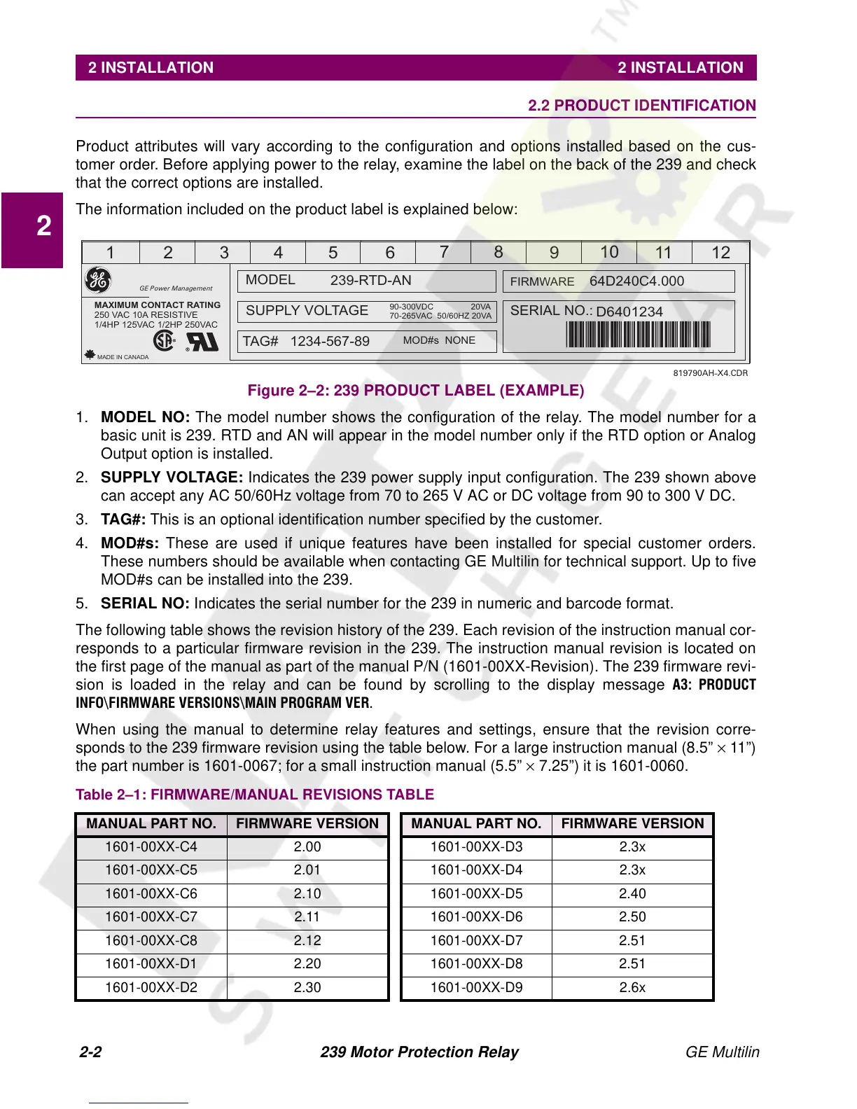
The information included on the product label is explained below:
Figure 2–2: 239 PRODUCT LABEL (EXAMPLE)
1. MODEL NO: The model number shows the configuration of the relay. The model number for a
basic unit is 239. RTD and AN will appear in the model number only if the RTD option or Analog
Output option is installed.
2. SUPPLY VOLTAGE: Indicates the 239 power supply input configuration. The 239 shown above
can accept any AC 50/60Hz voltage from 70 to 265 V AC or DC voltage from 90 to 300 V DC.
3. TAG#: This is an optional identification number specified by the customer.
4. MOD#s: These are used if unique features have been installed for special customer orders.
These numbers should be available when contacting GE Multilin for technical support. Up to five
MOD#s can be installed into the 239.
5. SERIAL NO: Indicates the serial number for the 239 in numeric and barcode format.
The following table shows the revision history of the 239. Each revision of the instruction manual cor-
responds to a particular firmware revision in the 239. The instruction manual revision is located on
the first page of the manual as part of the manual P/N (1601-00XX-Revision). The 239 firmware revi-
sion is loaded in the relay and can be found by scrolling to the display message
$ 352'8&7
,1)2?),50:$5(9(56,216?0$,1352*5$09(5
.
When using the manual to determine relay features and settings, ensure that the revision corre-
sponds to the 239 firmware revision using the table below. For a large instruction manual (8.5” × 11”)
the part number is 1601-0067; for a small instruction manual (5.5” × 7.25”) it is 1601-0060.
Table 2–1: FIRMWARE/MANUAL REVISIONS TABLE
MANUAL PART NO. FIRMWARE VERSION MANUAL PART NO. FIRMWARE VERSION
1601-00XX-C4 2.00 1601-00XX-D3 2.3x
1601-00XX-C5 2.01 1601-00XX-D4 2.3x
1601-00XX-C6 2.10 1601-00XX-D5 2.40
1601-00XX-C7 2.11 1601-00XX-D6 2.50
1601-00XX-C8 2.12 1601-00XX-D7 2.51
1601-00XX-D1 2.20 1601-00XX-D8 2.51
1601-00XX-D2 2.30 1601-00XX-D9 2.6x
110.000
SUPPLY VOLTAGE
TAG#
MOD#
®
NRTL
MAXIMUM CONTACT RATING
250 VAC 10A RESISTIVE
1/4 HP 125VAC 1/2HP 250VAC
12
11
10
9
8
7
654
3
2
1
MAXIMUM CONTACT RATING
250 VAC 10A RESISTIVE
1/4HP 125VAC 1/2HP 250VAC
MODEL
SUPPLY VOLTAGE SERIAL NO.:
TAG# 1234-567-89
90-300VDC 20VA
70-265VAC 50/60HZ 20VA
D6401234
239-RTD-AN
MADE IN CANADA
MOD#s NONE
FIRMWARE
64D240C4.000
GE Power Management
819790AH-X4.CDR