GE Multilin 239 Motor Protection Relay 2-1
2 INSTALLATION 2 INSTALLATION
2
239 INSTRUCTION MANUAL 2 INSTALLATION 2.1 MOUNTING
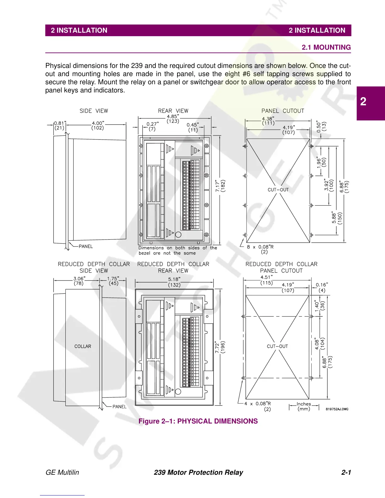
Physical dimensions for the 239 and the required cutout dimensions are shown below. Once the cut-
out and mounting holes are made in the panel, use the eight #6 self tapping screws supplied to
secure the relay. Mount the relay on a panel or switchgear door to allow operator access to the front
panel keys and indicators.
Figure 2–1: PHYSICAL DIMENSIONS