3-2 239 Motor Protection Relay GE Multilin
3 OPERATION 3 OPERATION
3
3.2 DISPLAY
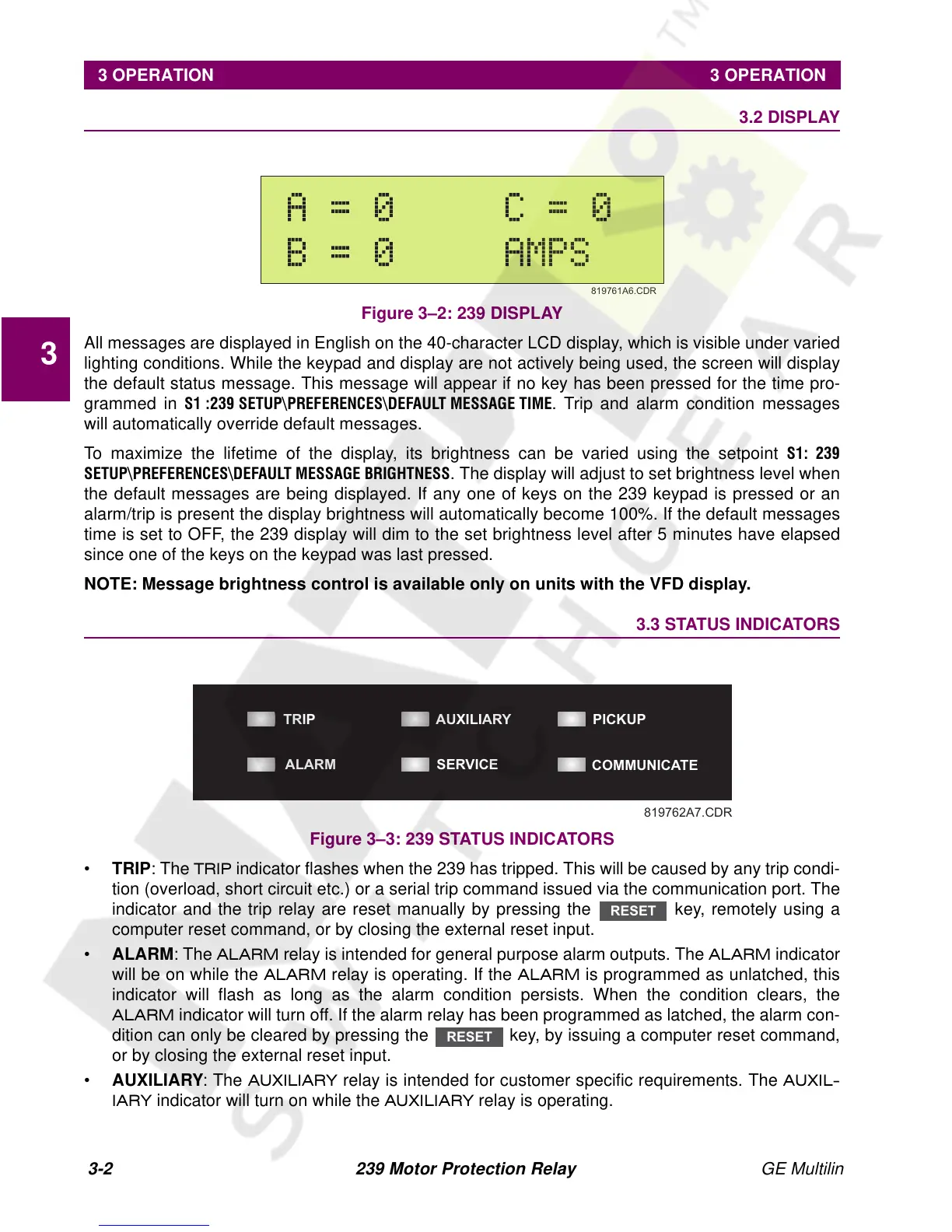
Figure 3–2: 239 DISPLAY
All messages are displayed in English on the 40-character LCD display, which is visible under varied
lighting conditions. While the keypad and display are not actively being used, the screen will display
the default status message. This message will appear if no key has been pressed for the time pro-
grammed in
6 6(783?35()(5(1&(6?'()$8/7 0(66$*( 7,0(. Trip and alarm condition messages
will automatically override default messages.
To maximize the lifetime of the display, its brightness can be varied using the setpoint
6
6(783?35()(5(1&(6?'()$8/70(66$*(%5,*+71(66
. The display will adjust to set brightness level when
the default messages are being displayed. If any one of keys on the 239 keypad is pressed or an
alarm/trip is present the display brightness will automatically become 100%. If the default messages
time is set to OFF, the 239 display will dim to the set brightness level after 5 minutes have elapsed
since one of the keys on the keypad was last pressed.
NOTE: Message brightness control is available only on units with the VFD display.
3.3 STATUS INDICATORS
Figure 3–3: 239 STATUS INDICATORS
• TRIP: The
75,3 indicator flashes when the 239 has tripped. This will be caused by any trip condi-
tion (overload, short circuit etc.) or a serial trip command issued via the communication port. The
indicator and the trip relay are reset manually by pressing the key, remotely using a
computer reset command, or by closing the external reset input.
• ALARM: The
$/$50 relay is intended for general purpose alarm outputs. The $/$50 indicator
will be on while the
$/$5 0 relay is operating. If the $/$5 0 is programmed as unlatched, this
indicator will flash as long as the alarm condition persists. When the condition clears, the
$/$50 indicator will turn off. If the alarm relay has been programmed as latched, the alarm con-
dition can only be cleared by pressing the key, by issuing a computer reset command,
or by closing the external reset input.
• AUXILIARY: The
$8; , /, $ 5 < relay is intended for customer specific requirements. The $8;, /
,$5<
indicator will turn on while the $8;,/,$5< relay is operating.
819761A6.CDR
TRIP
AUXILIARY
PICKUP
COMMUNICATE
SERVICEALARM
819762A7.CDR
RESET
RESET