GE Multilin 239 Motor Protection Relay 3-3
3 OPERATION 3 OPERATION
3
• SERVICE: Any abnormal condition detected during 239 self-monitoring, such as a hardware fail-
ure, will cause the
6(59,&( relay to operate. This relay is programmed to be failsafe (i.e. non-
operated state is "Energized," operated state is "De-energized"). The
6(59,&( indicator will turn
on while the
6(59,&( relay is operating (i.e. de-energized). Loss of control power to the 239
also causes the
6(59,&( relay to be de-energized, indicating that no protection is present.
• PICKUP: During testing, for calibration verification, it is useful to have an indication of when the
motor full load or ground trip pickup setting has been exceeded. Eventually an alarm or a trip will
occur if these conditions persist. The indicator will remain flashing as long as the motor full load
setting remains exceeded while the motor is running or ground current is above the ground trip
pickup level. The indicator will automatically turn off when the phase current drops below the full
load threshold and the ground current is below the trip pickup setting.
• COMMUNICATE: Status of the RS485 communication port is monitored with this indicator. If
there is no serial data being received via the rear serial port terminals the
&20081,&$7( indi-
cator will be off. This situation will occur if there is no connection, the serial wires have become
disconnected or the master computer is inactive. If there is activity on the serial port but the 239
is not receiving valid messages for its internally programmed address the indicator will flash. This
could be caused by incorrect message format such as baud rate or framing, reversed polarity of
the two RS485 twisted pair connections or the master not sending the currently programmed 239
address. If the 239 is being periodically addressed with a valid message, the
&20081,&$7 (
indicator will be on continuously. If no valid message has been received for 10 seconds, the indi-
cator will either flash (serial data present) or go off (no serial data).
3.4 KEYS
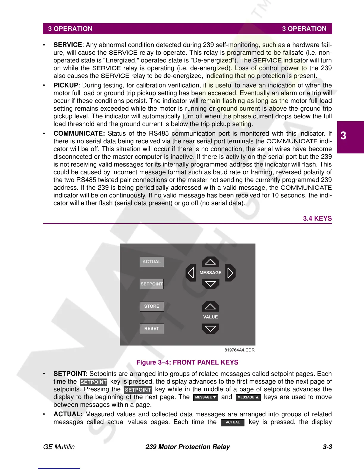
Figure 3–4: FRONT PANEL KEYS
• SETPOINT: Setpoints are arranged into groups of related messages called setpoint pages. Each
time the key is pressed, the display advances to the first message of the next page of
setpoints. Pressing the
key while in the middle of a page of setpoints advances the
display to the beginning of the next page. The and keys are used to move
between messages within a page.
• ACTUAL: Measured values and collected data messages are arranged into groups of related
messages called actual values pages. Each time the key is pressed, the display
819764A4.CDR
RESET
STORE
ACTUAL
VALUE
MESSAGE
SETPOINT
SETPOINT
MESSAGE
▼
MESSAGE
▲
ACTUAL