8-6 239 Motor Protection Relay GE Multilin
8 TESTING 8 TESTING
8
8.8 SWITCH INPUT
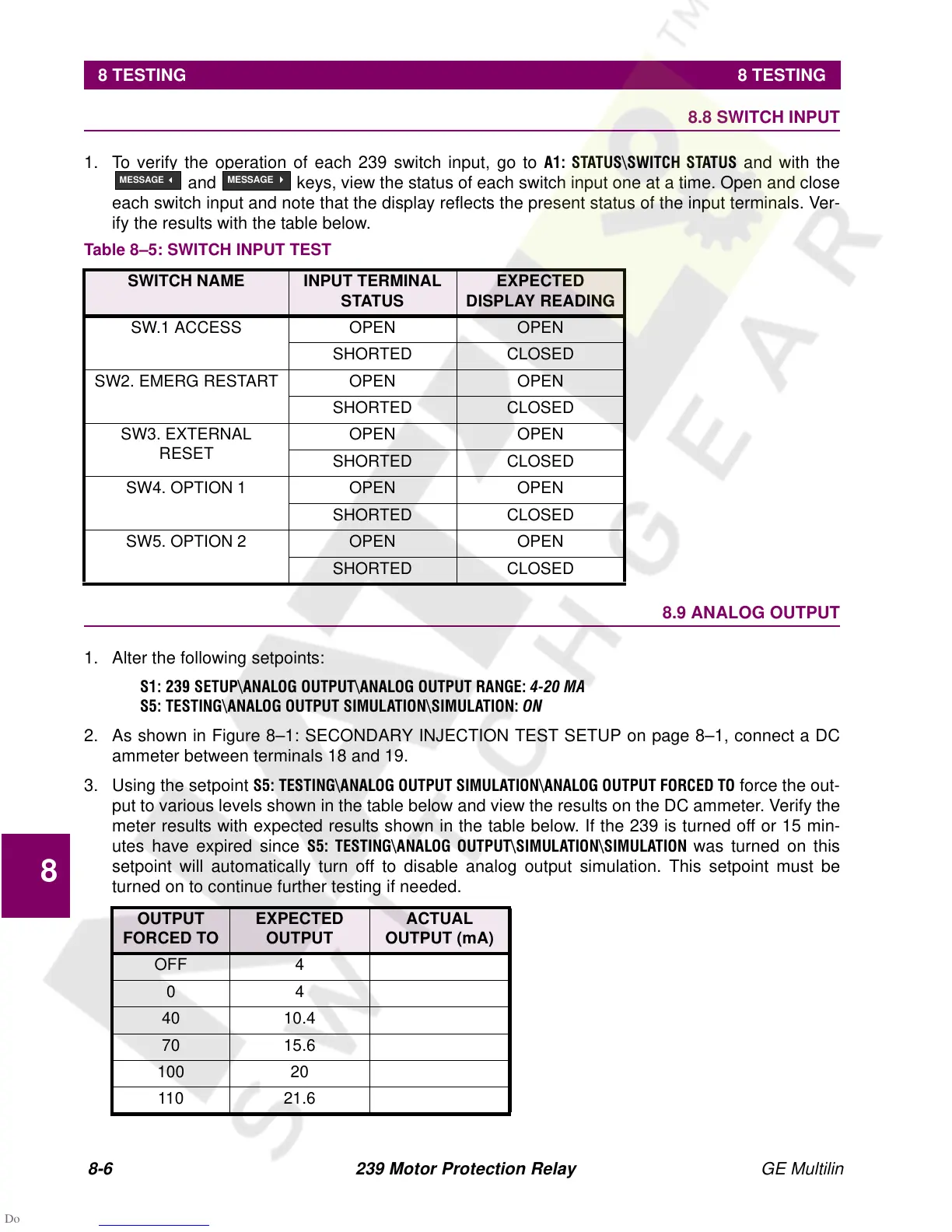
1. To verify the operation of each 239 switch input, go to
$ 67$786?6:,7&+ 67$786 and with the
and
keys, view the status of each switch input one at a time. Open and close
each switch input and note that the display reflects the present status of the input terminals. Ver-
ify the results with the table below.
8.9 ANALOG OUTPUT
1. Alter the following setpoints:
66(783?$1$/2*287387?$1$/2*2873875$1*(0$
67(67,1*?$1$/2*2873876,08/$7,21?6,08/$7,2121
2. As shown in Figure 8–1: SECONDARY INJECTION TEST SETUP on page 8–1, connect a DC
ammeter between terminals 18 and 19.
3. Using the setpoint
67(67,1*?$1$/2*2873876,08/$7,21?$1$/ 2*287387)25&('72 force the out-
put to various levels shown in the table below and view the results on the DC ammeter. Verify the
meter results with expected results shown in the table below. If the 239 is turned off or 15 min-
utes have expired since
6 7(67,1*?$1$/2* 287387?6,08/$7,21?6,08/$7,21 was turned on this
setpoint will automatically turn off to disable analog output simulation. This setpoint must be
turned on to continue further testing if needed.
Table 8–5: SWITCH INPUT TEST
SWITCH NAME INPUT TERMINAL
STATUS
EXPECTED
DISPLAY READING
SW.1 ACCESS OPEN OPEN
SHORTED CLOSED
SW2. EMERG RESTART OPEN OPEN
SHORTED CLOSED
SW3. EXTERNAL
RESET
OPEN OPEN
SHORTED CLOSED
SW4. OPTION 1 OPEN OPEN
SHORTED CLOSED
SW5. OPTION 2 OPEN OPEN
SHORTED CLOSED
OUTPUT
FORCED TO
EXPECTED
OUTPUT
ACTUAL
OUTPUT (mA)
OFF 4
04
40 10.4
70 15.6
100 20
110 21.6
MESSAGE
3
MESSAGE
4