GE Multilin 239 Motor Protection Relay 4-13
4 PROGRAMMING 4 PROGRAMMING
4
4.4 S3: OUTPUT RELAYS
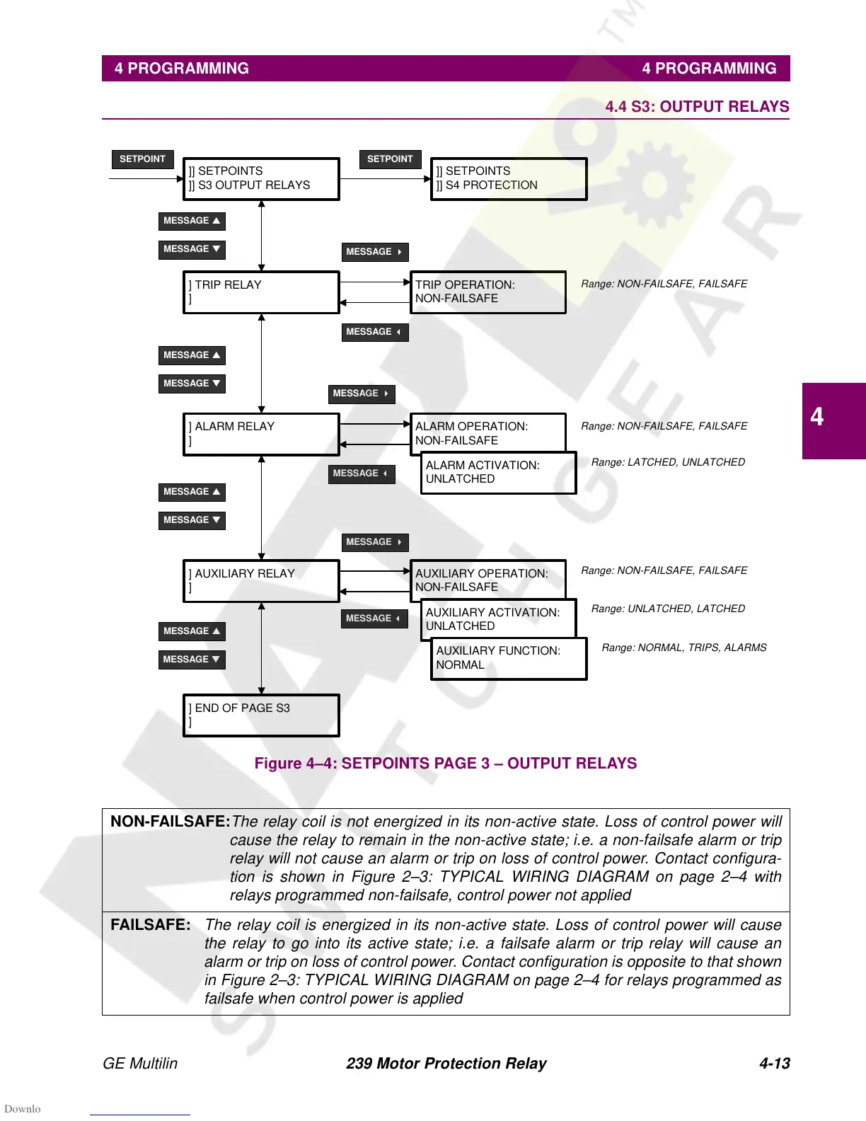
Figure 4–4: SETPOINTS PAGE 3 – OUTPUT RELAYS
NON-FAILSAFE:
The relay coil is not energized in its non-active state. Loss of control power will
cause the relay to remain in the non-active state; i.e. a non-failsafe alarm or trip
relay will not cause an alarm or trip on loss of control power. Contact configura-
tion is shown in Figure 2–3: TYPICAL WIRING DIAGRAM on page 2–4 with
relays programmed non-failsafe, control power not applied
FAILSAFE:
The relay coil is energized in its non-active state. Loss of control power will cause
the relay to go into its active state; i.e. a failsafe alarm or trip relay will cause an
alarm or trip on loss of control power. Contact configuration is opposite to that shown
in Figure 2–3: TYPICAL WIRING DIAGRAM on page 2–4 for relays programmed as
failsafe when control power is applied
]] SETPOINTS
]] S3 OUTPUT RELAYS
SETPOINT
MESSAGE
▼
] TRIP RELAY
]
MESSAGE
▲
TRIP OPERATION:
NON-FAILSAFE
] ALARM RELAY
]
ALARM OPERATION:
NON-FAILSAFE
ALARM ACTIVATION:
UNLATCHED
]] SETPOINTS
]] S4 PROTECTION
SETPOINT
Range: NON-FAILSAFE, FAILSAFE
MESSAGE
▲
MESSAGE
▲
MESSAGE
▼
MESSAGE
▼
MESSAGE
4
MESSAGE
4
MESSAGE
4
MESSAGE
3
MESSAGE
3
] AUXILIARY RELAY
]
AUXILIARY OPERATION:
NON-FAILSAFE
AUXILIARY ACTIVATION:
UNLATCHED
AUXILIARY FUNCTION:
NORMAL
] END OF PAGE S3
]
MESSAGE
3
MESSAGE
▲
MESSAGE
▼
Range: NON-FAILSAFE, FAILSAFE
Range: LATCHED, UNLATCHED
Range: NON-FAILSAFE, FAILSAFE
Range: UNLATCHED, LATCHED
Range: NORMAL, TRIPS, ALARMS