4-12 239 Motor Protection Relay GE Multilin
4 PROGRAMMING 4 PROGRAMMING
4
above. In between these two extremes there is a linear relationship; the 239 thermal model cov-
ers the entire range of motor temperatures: cold—cool—warm—hot. The steady state value of
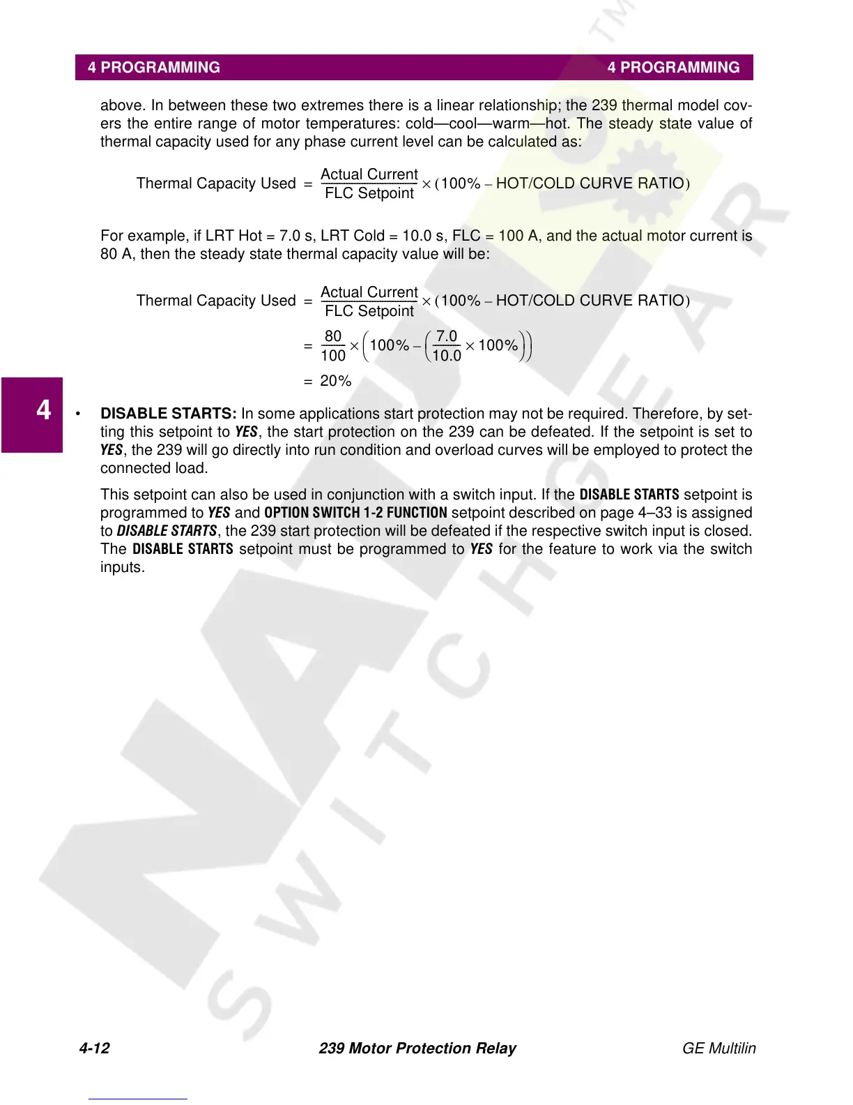
thermal capacity used for any phase current level can be calculated as:
For example, if LRT Hot = 7.0 s, LRT Cold = 10.0 s, FLC = 100 A, and the actual motor current is
80 A, then the steady state thermal capacity value will be:
• DISABLE STARTS: In some applications start protection may not be required. Therefore, by set-
ting this setpoint to
<(6, the start protection on the 239 can be defeated. If the setpoint is set to
<(6, the 239 will go directly into run condition and overload curves will be employed to protect the
connected load.
This setpoint can also be used in conjunction with a switch input. If the
',6$%/(67$576 setpoint is
programmed to
<(6 and 237,216:,7&+ )81&7,21 setpoint described on page 4–33 is assigned
to
',6$%/(67$576, the 239 start protection will be defeated if the respective switch input is closed.
The
',6$%/(67 $576 setpoint must be programmed to <(6 for the feature to work via the switch
inputs.
Thermal Capacity Used
Actual Current
FLC Setpoint
--------------------------------------
100% HOT/COLD CURVE RATIO
–
()×
=
Thermal Capacity Used
Actual Current
FLC Setpoint
--------------------------------------
100% HOT/COLD CURVE RATIO
–
()×
=
80
100
----------
100%
7.0
10.0
-----------
100%×
–
×
=
20%
=