GE Multilin 239 Motor Protection Relay 2-11
2 INSTALLATION 2 INSTALLATION
2
h) ANALOG OUTPUT (OPTION) (18/19/20)
Terminals 18-20 of the 239 are available for a single analog current output of one parameter. Verify
that the Analog Output option is installed by noting that the product identification label on back of the
relay includes -AN in the order code. The choice of output and current range is selected in
6
6(783?$1$/2*287387?$1$/2*2873877<3(5$1*(
. Use the TYPE message to select one of the fol-
lowing for output: phase CT (secondary) amps, % motor full load current (FLC), thermal capacity
used (100% = motor tripped), RTD1 temperature, RTD2 temperature, or RTD3 temperature. The
RANGE message selects the output current as: 0-1 mA, 0-20 mA or 4-20 mA. Range assignment is
shown below in Table 2–4: ANALOG OUTPUT RANGE ASSIGNMENT.
This output is a current source suitable for connection to a remote meter, chart recorder, programma-
ble controller, or computer load. Use the 4-20 mA with a programmable controller that has a current
input. If only a voltage input is available use a scaling resistor at the PLC terminals to scale the cur-
rent to the equivalent voltage and select the 0 to 20 mA output. For example, install a 500 Ω resistor
across the terminals of a 0 to 10 V input to make the 0 to 20 mA output correspond to 0 to 10V (R =
V/I = 10 V / 0.02 A = 500 Ω). When the GE Multilin TCS2 thermal capacity meter is connected to the
terminals, select the 0 to 1 mA range. Current levels are not affected by the total lead and load resis-
tance which must not exceed 600 Ω for 0-20 mA and 4-20mA range and 2400 Ω for 0-1mA range.
For readings greater than full scale the output will saturate at 21 mA (0-20/4-20 range) or 1.1 mA (0-
1 range). This analog output is isolated. Since both output terminals 18 and 19 are floating, the con-
nection of the analog output to a process input will not introduce a ground loop. Part of the system
should be grounded for safety, typically at the programmable controller. For floating loads, such as a
meter, ground terminal 19 externally. Terminal 20 is internally grounded and may be used as a shield
ground if required. Ground the shield at one end only to prevent ground loop noise.
i) SERIAL PORT (15/16/17)
A serial port provides communication capabilities between the 239 and a remote computer, PLC or
distributed control system (DCS). Up to thirty-two 239 relays can be daisy chained together with 24
AWG stranded, shielded, twisted pair wire on a single communication channel. Suitable wire should
have a characteristic impedance of 120 Ω such as Belden #9841. These wires should be routed
away from high power AC lines and other sources of electrical noise. The total length of the commu-
nications wiring should not exceed 4000 feet for reliable operation. Correct polarity is essential for
the communications port to operate. Terminal 15 (485 A+) of every 239 in a serial communication link
must be connected together. Similarly, terminal 16 (485 B-) of every 239 must also be connected
together. These polarities are specified for a 0 logic and should match the polarity of the master
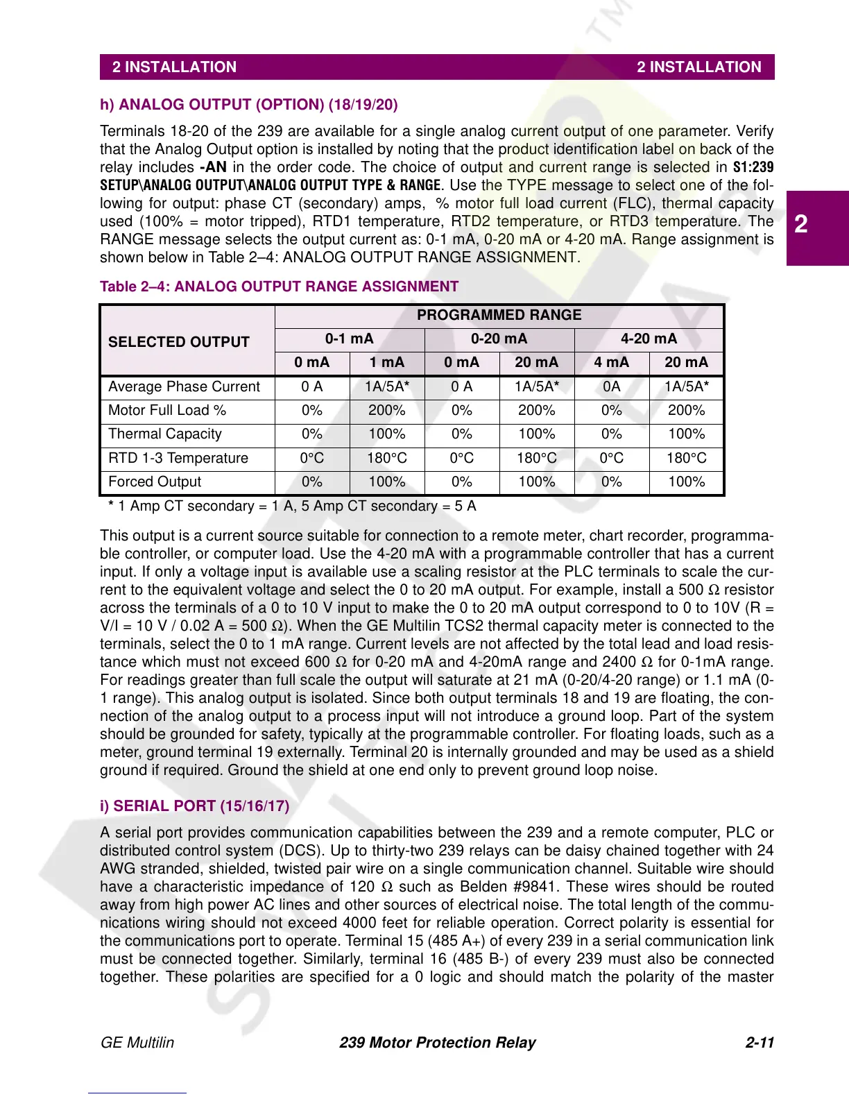
Table 2–4: ANALOG OUTPUT RANGE ASSIGNMENT
SELECTED OUTPUT
PROGRAMMED RANGE
0-1 mA 0-20 mA 4-20 mA
0 mA 1 mA 0 mA 20 mA 4 mA 20 mA
Average Phase Current 0 A 1A/5A* 0 A 1A/5A* 0A 1A/5A*
Motor Full Load% 0%200%0%200%0%200%
Thermal Capacity 0% 100% 0% 100% 0% 100%
RTD 1-3 Temperature 0°C180°C0°C180°C0°C180°C
Forced Output 0% 100% 0% 100% 0% 100%
* 1 Amp CT secondary = 1 A, 5 Amp CT secondary = 5 A