A-2 735/737 Feeder Protection Relay
GE Power Management
A.2 FEEDER DEDICATED TO A TRANSFORMER APPENDIX A
A
A.2 FEEDER DEDICATED TO A TRANSFORMER A.2.1 CHARACTERISTICS
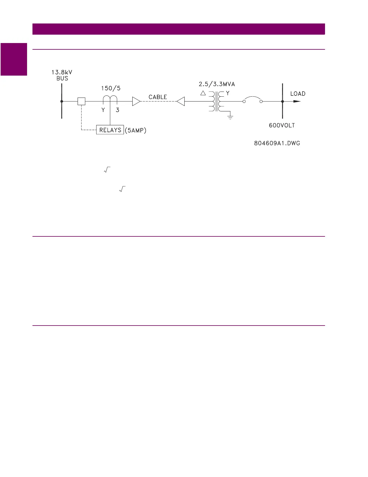
Feeder Dedicated to a Transformer:
From short circuit study:
• Maximum load current = = 138 A
• Maximum transformer inrush = = 1255 A
•3Φ fault in high voltage cable = 1760 A
• Ground fault in high voltage cable = 2100 A
•3Φ fault in 600 V cable = 20600 A
A.2.2 PHASE TIMED O/C PICKUP
The phase time overcurrent pickup is approximately equal to 1.2 to 1.5 times the maximum current, for example: 1.3 × 138
A = 179.4 A. Thus,
• Phase Pickup dial setting = = 120%
From time coordination curves established in the coordination study, with a minimum coordination between devices of 0.3
seconds (normally between 0.2 and 0.5 seconds), determine curve shape and time multiplier.
• Phase Curve Shape dial setting = VERY INVERSE
• Phase Time Multiplier dial setting = 3
A.2.3 PHASE INSTANTANEOUS
It is desirable to operate this protection for a fault on the 600V bus.
• Fault current at 13.8 kV = = 895 Amps
This current is less than the maximum possible transformer inrush current of 1255 A. Thus this value cannot be used.
Instead set instantaneous pickup at 120% of inrush level.
Instantaneous pickup current level = 1.2 × 1255 = 1506 A
Phase Instantaneous dial setting = 1506 A / 150 A ≈ 10
3300 kVA
3 13.8 kV×
----------------------------------
2500 kVA
3 13.8 kV×
----------------------------------
12×
179.4 A
150 A
---------------------
100×
20600 A 600 A×
13800 A
------- ----------------------- --------------- 895 A=