2-12 735/737 Feeder Protection Relay
GE Power Management
2.2 ELECTRICAL 2 INSTALLATION
2
2.2.6 SYSTEM GROUNDING
Two separate grounds are brought out to rear terminals. The safety ground (terminal G12) makes a solid electrical connec-
tion to all internal metal chassis parts and causes a fuse to blow should a short develop to the case. It ensures operator
safety in the event of a fault. A separate green ground screw is also provided on the back of the chassis for the safety
ground.
Surge suppression components are grounded to a separate filter ground (terminal G11). These components are designed
to conduct during transients at input terminals to prevent nuisance operation or damage to internal components. For reli-
able operation both grounds must be tied directly to the ground bus bar of the switchgear which is itself connected to a solid
ground. Braided cable or heavy solid copper wire (such as 10 gauge) should be used for optimum transient protection. Do
not rely on a ground connection to a part of the metal switchgear enclosure because a low impedance to ground cannot be
guaranteed.
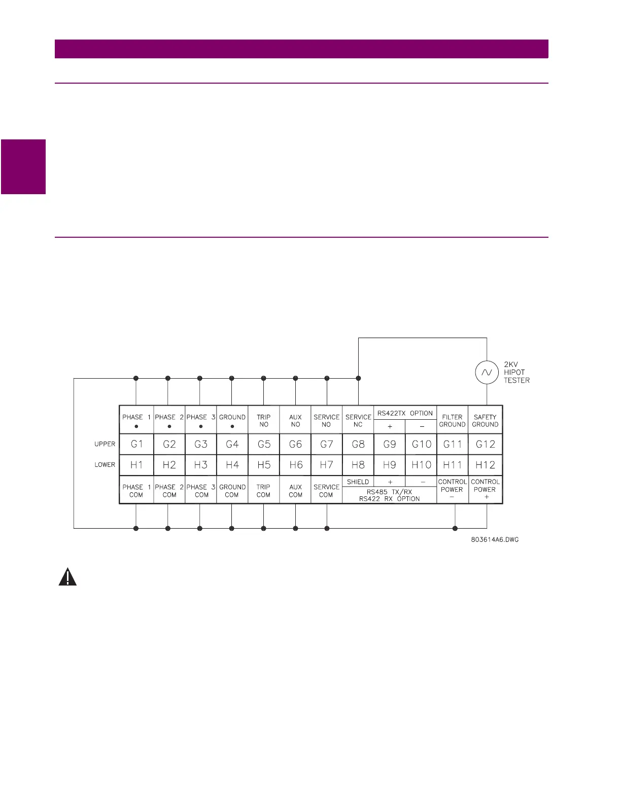
2.2.7 HI-POT TESTING
Prior to leaving the factory, all terminals except filter ground and communications are hi-pot (dielectric strength) tested. If hi-
pot testing is to be performed on an installed relay for insulation verification. The hi-pot potential is applied between the
wired together terminals and the enclosure ground according to the figure below. A potential of 2.0 kV is to be applied for 1
minute to test dielectric strength. To effectively clamp transient voltages at a level sufficient to protect the internal circuitry,
the internal transient protection devices conduct below the hi-pot voltages used for insulation testing. Consequently, the fil-
ter ground terminal G11 must be left floating for this test.
Figure 2–15: HI-POT TESTING CONNECTIONS
Disconnect the communications terminals and filter ground during dielectric strength testing (hipot) or
damage to the internal surge protection devices may occur.
WARNING