GE Power Management 735/737 Feeder Protection Relay 1-
7
1 INTRODUCTION 1.3 SPECIFICATIONS
1
1.3.3 OUTPUTS
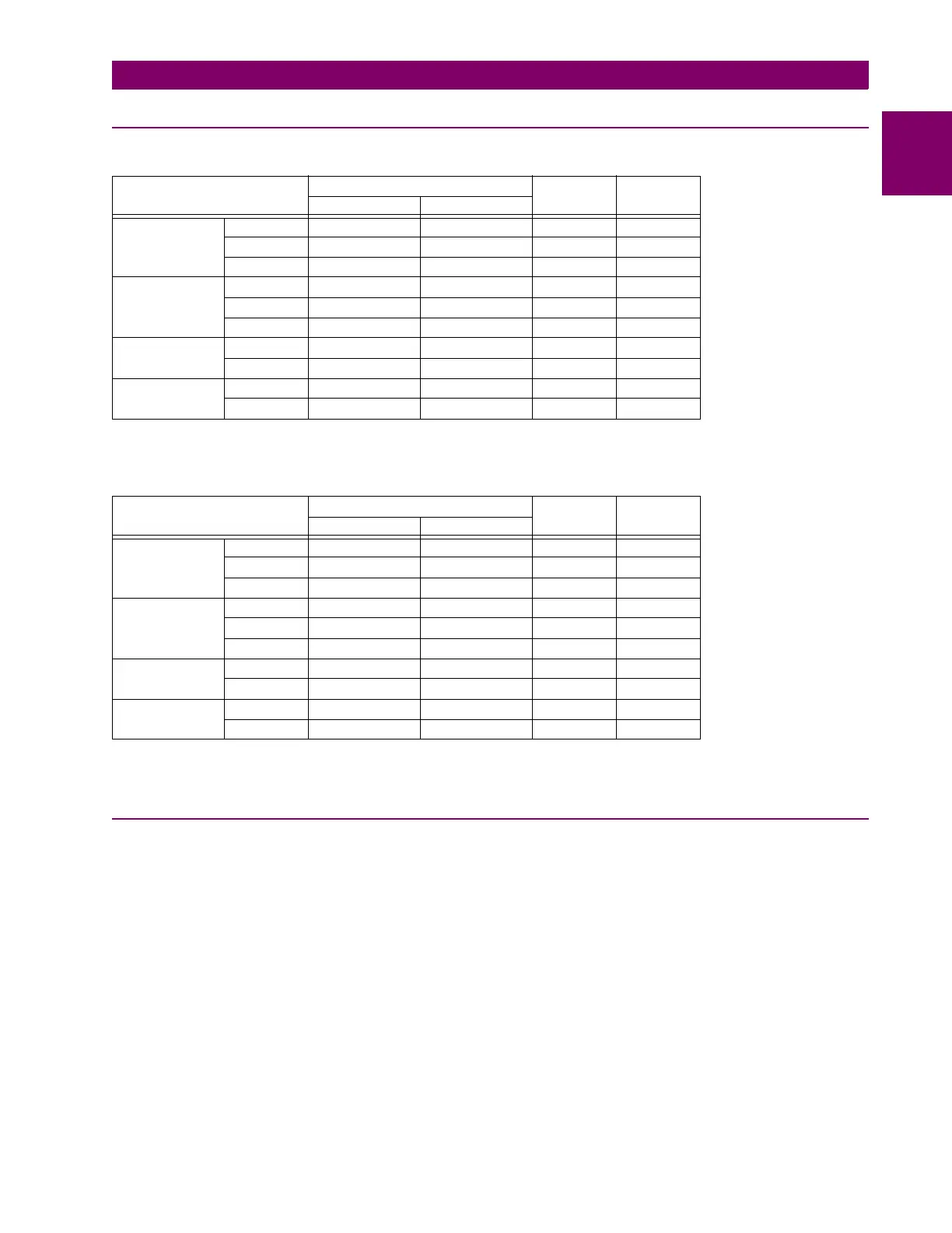
TRIP, AUX TRIP OUTPUT RELAYS
Confi
uration: Form A NO
Contact Material: Silver Alloy
SERVICE, PICKUP/CAUSE OF TRIP OUTPUT RELAYS
Confi
uration: Form C NO/NC
Contact Material: Silver Alloy
1.3.4 POWER SUPPLY
CONTROL POWER
DC supply: HI: 125 V DC, 250 V DC nominal
LO: 48 V DC nominal
Ran
e: HI: 90 to 300 VDC, 70 to 265 V AC
LO: 20 to 60 V DC, 20 to 48 V AC
Power: nominal 10W, maximum 25W
VOLTAGE MAKE/CARRY BREAK MAX LOAD
CONTINUOUS 0.2 S
DC Resistive 30 V DC 20 A 80 A 16 A 480 W
125 V DC 20 A 80 A 0.8 A 100 W
250 V DC 20 A 80 A 0.4 A 100 W
DC Inductive,
L/R = 40 mS
30 V DC 20 A 80 A 5 A 150 W
125 V DC 20 A 80 A 0.3 A 375 W
250 V DC 20 A 80 A 0.2 A 50 W
AC Resistive 120 V AC 20 A 80 A 20 A 2400 VA
250 V AC 20 A 80 A 20 A 5000 VA
AC Inductive
PF = 0.4
120 V AC 20 A 80 A 8 A 960 VA
250 V AC 20 A 80 A 7 A 1750 VA
VOLTAGE MAKE/CARRY BREAK MAX LOAD
CONTINUOUS 0.2 S
DC Resistive 30 V DC 10 A 30 A 10 A 300 W
125 V DC 10 A 30 A 0.5 A 62.5 W
250 V DC 10 A 30 A 0.3 A 75 W
DC Inductive,
L/R = 40 mS
30 V DC 10 A 30 A 5 A 150 W
125 V DC 10 A 30 A 0.25 A 31.3 W
250 V DC 10 A 30 A 0.15 A 37.5 W
AC Resistive 120 V AC 10 A 30 A 10 A 2770 VA
250 V AC 10 A 30 A 10 A 2770 VA
AC Inductive
PF = 0.4
120 V AC 10 A 30 A 4 A 480 VA
250 V AC 10 A 30 A 3 A 750 VA