GE Power Management 735/737 Feeder Protection Relay 2-
11
2 INSTALLATION 2.2 ELECTRICAL
2
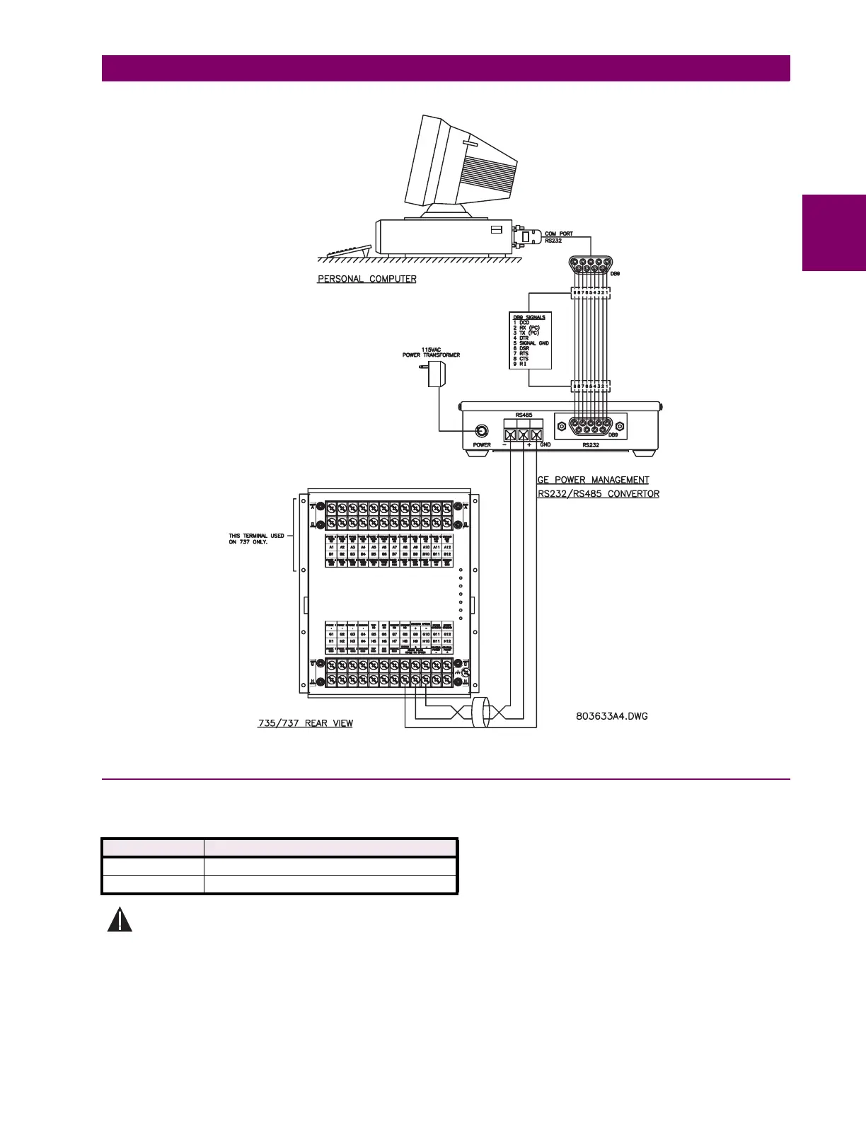
Figure 2–14: RS232/485 CONVERTER
2.2.5 CONTROL POWER
Control power supplied to the 735/737 must match the switching power supply installed or damage to the unit will occur.
Consult the order code from the label on the side of the drawout chassis. It will specify the nominal control voltage as:
Ensure applied the control voltage and rated voltage on drawout case terminal label match to prevent dam-
age.
For example, the 125/250 power supply will work with any voltage from 90 to 300 V DC or AC voltage from 70 to 265 V AC.
The internal fuse may blow if too high a voltage is applied resulting in a completely dead relay. If this occurs the RELAY IN
SERVICE indicator will be off and the service output contacts will indicate a relay malfunction. Polarity is not important with
DC voltage.
NOMINAL RANGE
24/48 20 to 60 V DC; 20 to 28 V AC at 50/60 Hz
125/250 90 to 300 V DC; 70 to 265 V AC at 50/60 Hz