GE Power Management
735/737 Feeder Protection Relay 3-1
3 SETUP AND OPERATION 3.1 FRONT PANEL
3
3 SETUP AND OPERATION 3.1 FRONT PANEL 3.1.1 DESCRIPTION
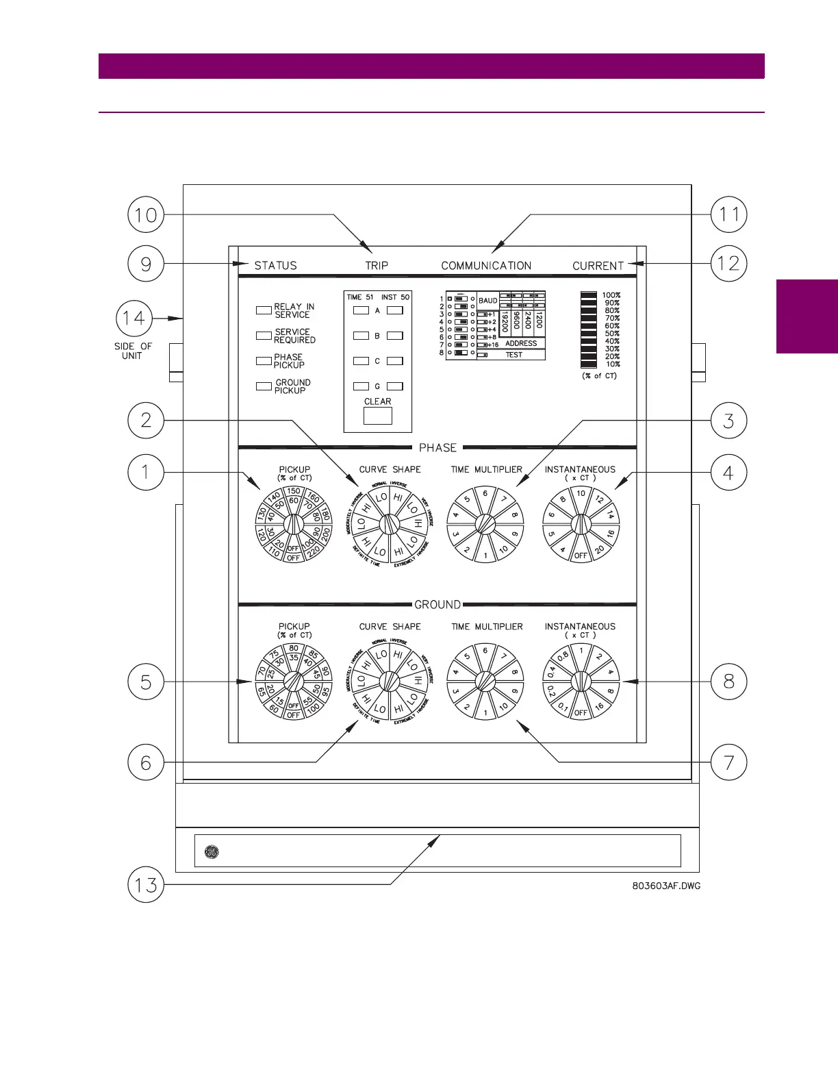
A front panel view of the 735/737 relay is shown below. An explanation of each of the numbered controls/indicators is con-
tained in the following sections.
Figure 3–1: FRONT PANEL CONTROLS AND INDICATORS
735 Feeder Protection Relay