GE Power Management
735/737 Feeder Protection Relay 3-13
3 SETUP AND OPERATION 3.5 SETUP PROGRAM
3
3.5.4 SYSTEM CONFIGURATION
SYSTEM CONFIGURATION > PORT:
Enter the computer COM port that is being used for communication to the relay. Usually this will be COM1:
SYSTEM CONFIGURATION > DISPLAY:
Color, monochrome, and black and white displays are supported by the
735SETUP
program. Select the display type that
best matches the computer system used.
INFO:
Product features are displayed in this screen for reference. No operation is performed when this menu item is selected.
QUIT:
Exit the
735SETUP
program back to DOS
3.5.5 STATUS
Once communication with the relay is established menus are used for direct communication with the relay to read actual
values, read settings and simulate relay operation. When screen values are changed, the modified data is sent immediately
to the connected relay. These menu items are shown and described below.
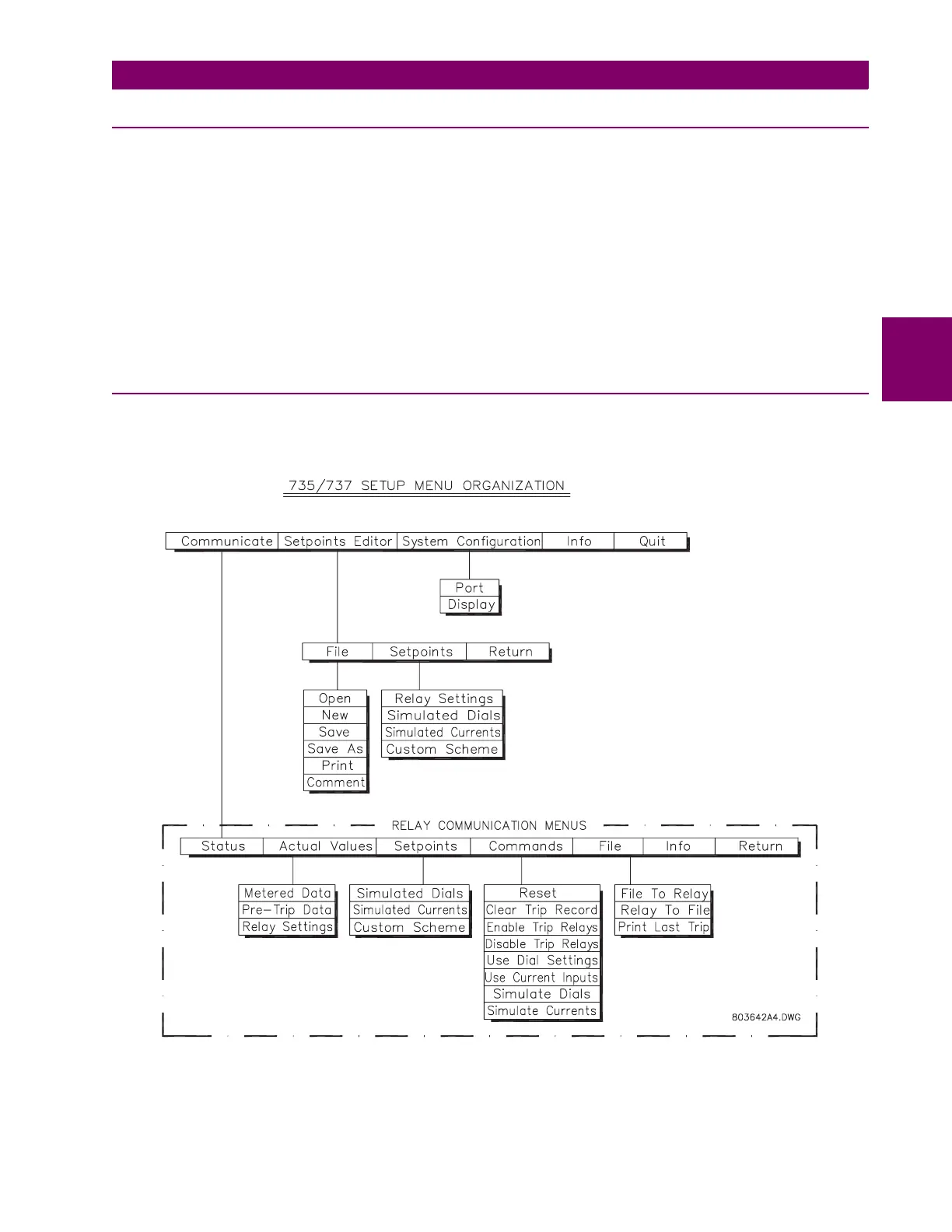
Figure 3–11: SETUP SOFTWARE RELAY COMMUNICATION MENUS
The computer screen is a mimic of the relay front panel indicators. It shows status, pickup, cause of trip indicators and the
current bargraph. The computer screen information is constantly updated to agree with the relay front panel indications.